Operation – KROHNE OPTIWAVE 5200C SIL User Manual
Page 17
OPERATION
7
17
OPTIWAVE 5200 C
www.krohne.com
02/2013 - 4001906202 - AD SIL OPTIWAVE 5200 R02 en
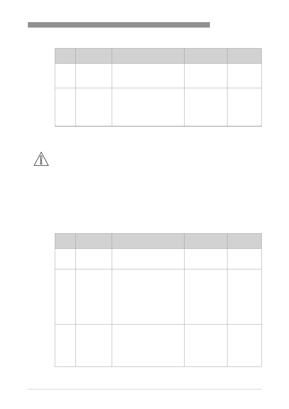
7.5.2 Limits for supervisor menu functions related to device configuration
2.3.8
ANTENNA.TYP
Type of antenna. For more data,
refer to the "Technical data"
chapter in the handbook.
PP Horn,
PTFE Horn,
Metal. Horn,
Wave Stick,
Wave Guide
1
2.3.9
DIST.PIECE
Optional distance piece between
the converter and the process
connection. This is for high-
temperature applications more
than +150°C / +302°F. The distance
piece is 120 mm / 4.7¨ long. For
more data, refer to the "Technical
data" chapter in the handbook.
min:
0 mm / 0¨
max:
2.3.1 TANK HEIGHT
1
1 This value is given in the customer order data
Menu
No.
Function
Function description
Selection list
Default value
and comments
CAUTION!
Make sure that you have the device configuration that follows:
•
2.6.1 HART ADDRESS is set to "0". If it is not set to "0", the safety function will not operate
correctly.
•
2.4.2 RANGE I is set to "4-20 / 3.6E" or "3.8-20.5 / 3.6E". If the error signal is set to "22 mA" or
"Hold", the safety function will not operate correctly.
•
2.5.4 MEASUR.MODE is set to "Direct". If the error signal is set to "TBF Partial" or "TBF Full",
the safety function will not operate correctly.
•
2.2.1 SET OUTPUT is not shown on the device display or in PACTware. If SET OUTPUT is
shown, the output will change to the set test value, independent of the measured value. The
current output will go back to the measured value when the user makes the display or
PACTware go back to the menu level.
Menu
No.
Function
Function description
Selection list
Default value
and comments
2.3.1
TANK HEIGHT
The distance from the tank
connecting flange face / thread
stop down to the tank bottom.
min-max:
1…30 m /
3.3…98.4 ft
Default value
agrees with the
customer
order
2.4.1
OUTPUT FUNC.
The output function. Select an
output function to scale the current
values in relation to a given point
(usually the device process
connection or the tank bottom). The
output current value is shown on a
bar graph in normal mode if the
measurement name is the same as
the output function. Conversion
parameters are shown if there is
volume or mass data in 2.8.1 INPUT
TABLE.
Distance, Level,
Distance
conversion,
Level conversion
Default value
agrees with the
customer
order
2.4.2
RANGE I
This parameter sets the range of
the output current with
(3.8...20.5 mA) or without
(4...20 mA) over-run values. It also
tells the device what to do if an
error occurs. For example, the
device will change to an error value
of 3.6 mA if you set RANGE I to
"3.8-20.5/3.6E".
4-20, 4-20 / 22E,
4-20 / 3.6E,
3.8-20.5 / 22E,
3.8-20.5 / 3.6E
3.8-20.5 / 3.6E
1