I+ i, Ri ≤ 500 ω, B1 b ⊥ b2 – KROHNE ALTOFLUX IFM x080 K ATEX EN User Manual
Page 14
ALTOFLUX IFM x080 K-EEx and ALTOFLUX IFM x080 K / i-EEx
14
2.4
Regular IFC 090-EEx electronics unit
The field cables that enter the terminal compartment of the IFC 090-EEx signal converter unit (i.e.
power supply, current and binary outputs) are non-intrinsically safe. To connect external devices
to the signal output terminals, the wiring requirements for the type of protection of the
compartment (standard: increased safety "e", optional: flameproof "d") must be conform to the
international or national standard involved (e.g. EN 60079-14).
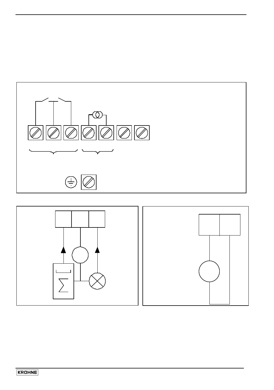
The terminal arrangement is shown by figure 1 below.
Terminal arrangement in terminal compartment
B1
B
⊥
B2
I+
I
L
N
(100…240Vac / 48…63 Hz)
L½ L½ (24Vac/dc)
BINARY
CURRENT
OUTPUTS
OUTPUT
PE (Protective Earth) terminal
FE (Functional Earth) terminal
PULSE, STATUS OUTPUTS
RESP. CONTROL INPUTS
Passive pulse/status output
½
B1 B
⊥
B2
I
≤
150 mA
U
ext
≤
32Vdc/24 Vac
000
Electronic or
electro-
mechanical
totalizer
I
≤
150 mA
U
ext
e.g. signal
indicator
Active current output
Note:
The binary outputs (terminals B1, B
⊥
and B2) can only be configured as passive
outputs, the current output (terminals I+ and I) can only be configured as active output.
Ri
≤
500
Ω
I+
I
mA
+
_
IFS x000 … - EEx
Primary head