Hazardous locations of zone 1 and 2, Option: modis – KROHNE ALTOFLUX IFM x080 K ATEX EN User Manual
Page 13
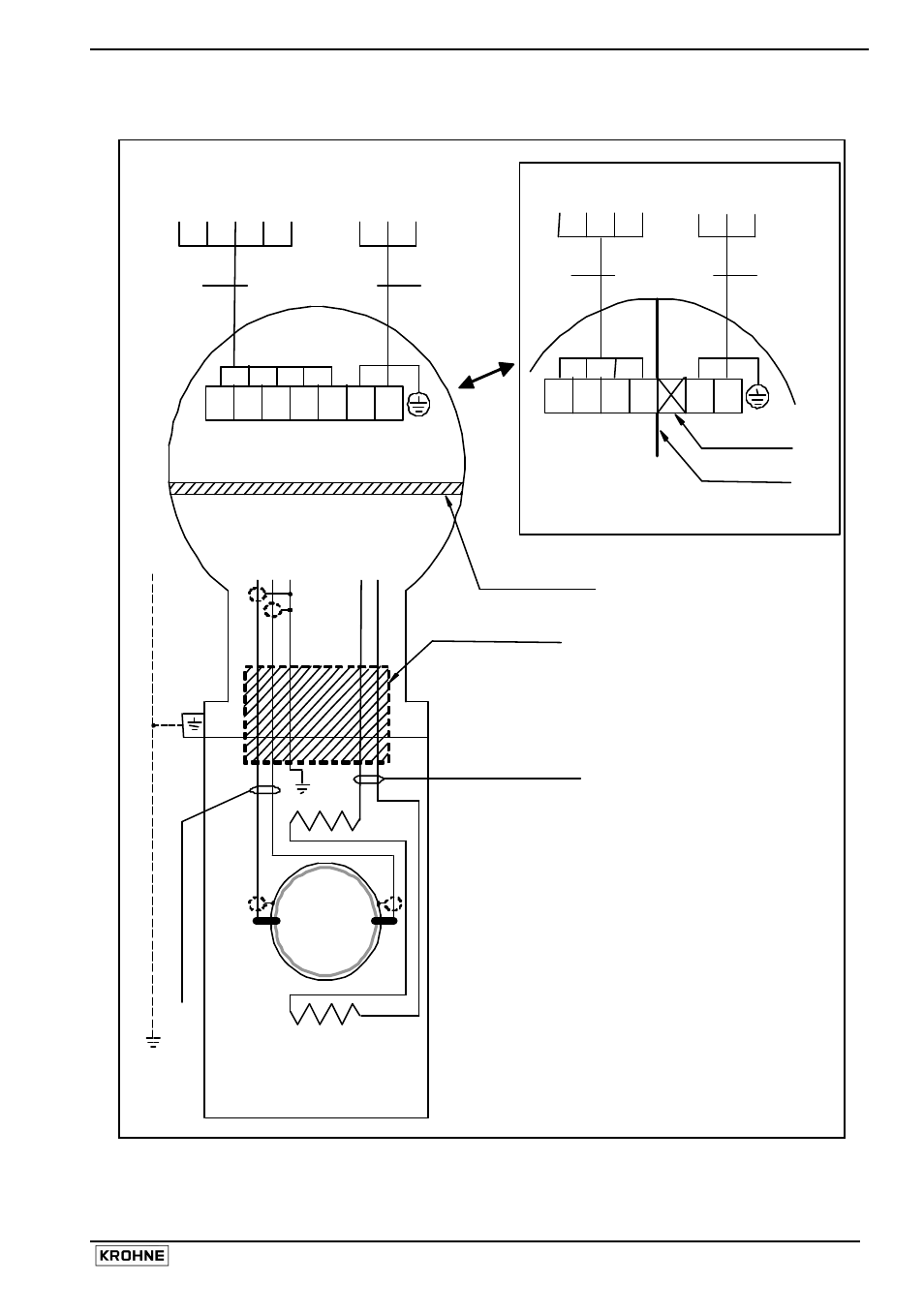
ALTOFLUX IFM x080 K-EEx and ALTOFLUX IFM x080 K / i-EEx
13
2.3
Connection diagram
Flow tube
Hazardous locations
of Zone 1 and 2
E
IFS 4000…-EEx
Primary Head
Intrinsically safe electrode circuits
Increased safe field coil circuit
Coil
B1 B
⊥
B2 I+ I L N
BINARY
CURRENT MAINS
OUTPUTS
OUTPUT SUPPLY
TERMINAL COMPARTMENT
Standard "EEx e" (Optional "EEx d")
ELECTRONICS COMPARTMENT (always "EEx d")
electrode circuits
field coil circuits
IFC 090-EEx
Signal Converter
PE
FE
L
N
PE 100-230 Vac
SIGNAL IN-/OUTPUTS
L
½
L
½ FE 24 Vac/dc
EQUIPOTENTIAL BONDING CONDUCTOR
≥
4 mm
2
(OPTIONAL)
Flameproof (EEx d) cable
feed-through
Field coil wires
B
A
E
Coil
Electrode cables
IFC 090i-EEx
Signal Converter
x x x x
1L½ 0L½
PE
FE
INTRINSICALLY SAFE
SIGNAL IN-/OUTPUTS
L
N PE 100-230 Vac
(i.e. MODIS)
L
½ L½
FE
24 Vac/dc
Separation plate
Unused terminal
OPTION: MODIS
Flameproof (EEx d)
terminal feed-through
B
A
- BATCHFLUX 5500 C Quickstart EN (20 pages)
- IFC 050 Converter Quickstart EN (28 pages)
- IFC 100 Converter Quickstart EN (32 pages)
- IFC 300 Converter Quickstart EN (68 pages)
- OPTIFLUX 1000 Quickstart EN (20 pages)
- OPTIFLUX 2000 Quickstart EN (24 pages)
- OPTIFLUX 4000 Quickstart EN (24 pages)
- OPTIFLUX 4040C Quickstart EN (16 pages)
- OPTIFLUX 5000 Flange Quickstart EN (20 pages)
- OPTIFLUX 5000 Sandwich Quickstart EN (20 pages)
- OPTIFLUX 6000 Quickstart EN (28 pages)
- OPTIFLUX 7300 Quickstart EN (24 pages)
- OPTIPROBE Quickstart EN (16 pages)
- TIDALFLUX 2300 F EN (44 pages)
- TIDALFLUX 2300 F Quickstart EN (24 pages)
- WATERFLUX 3000 EN (40 pages)
- WATERFLUX 3000 Quickstart EN (24 pages)
- WATERFLUX 3070 EN (80 pages)
- WATERFLUX 3070 Quickstart EN (32 pages)
- USB ADAPTER PLUS EMF EN (16 pages)
- IFC 050 Converter Modbus EN (20 pages)
- IFC 100 Converter FOUNDATION FIELDBUS EN (64 pages)
- IFC 100 Converter Modbus EN (20 pages)
- IFC 300 Converter FOUNDATION FIELDBUS EN (60 pages)
- IFC 300 Converter HART 0102 EN (20 pages)
- IFC 300 Converter HART 0201 EN (23 pages)
- IFC 300 Converter Modbus EN (24 pages)
- IFC 300 Converter PROFIBUS PA DP EN (40 pages)
- OPTIFLUX 2000-4000 IECEx EN (16 pages)
- OPTIFLUX 2000-4000-5000-6000-7300-IFC 300 Ex EN (40 pages)
- OPTIFLUX 2000-4000-5000-6000 -IFC 100 Ex EN (24 pages)
- OPTIFLUX 4040 C Ex EN (20 pages)
- OPTIFLUX x300 Ex Zone2 EN (1 page)
- H250 M9 ES EN (36 pages)
- VA 40-VA 45 EN (36 pages)
- H250 M10 ATEX II2G Ex d EN (16 pages)
- H250 M10 ATEX II3D Ex t EN (16 pages)
- H250 M40 ATEX II2D Ex t-II2G Ex d EN (20 pages)
- H250 M40 ATEX II2G Ex i EN (20 pages)
- H250 M40 ATEX II3G Ex nA EN (20 pages)
- H250 M40 Ex II2G Reed EN (2 pages)
- H250 M9 ATEX II2G Ex i EN (16 pages)
- H250 M9S ATEX II3D Ex t-II3G Ex nA EN (20 pages)
- M8E Converter HART 0101 EN (13 pages)
- DK 32-DK 34 ATEX II2G Ex i EN (16 pages)