KROHNE IFC 210 E Short EN User Manual
Page 16
Sect. 2.5
Part A System installation and start-up
16
IFC 210 E
05/2002
2.5
Connection diagrams for outputs and inputs
Important:
In respect of EEx versions, pay regard to all directions marked with the
symbol,
and also the information given in Sect. 6.1 and 13.
Only the EEx primary head may be installed in the hazardous area.
The signal converter must be installed outside the hazardous area!
Please note ! Unwired contacts may not have
any conductive connection with other electrically
conducting parts.
Electrical connection to socket connector XC
Wiring diagrams
c
to
l
of outputs and inputs.
Interface operation with HART
®
or
RS 485 (Option) see Sect. 6.2.1 and 6.2.2.
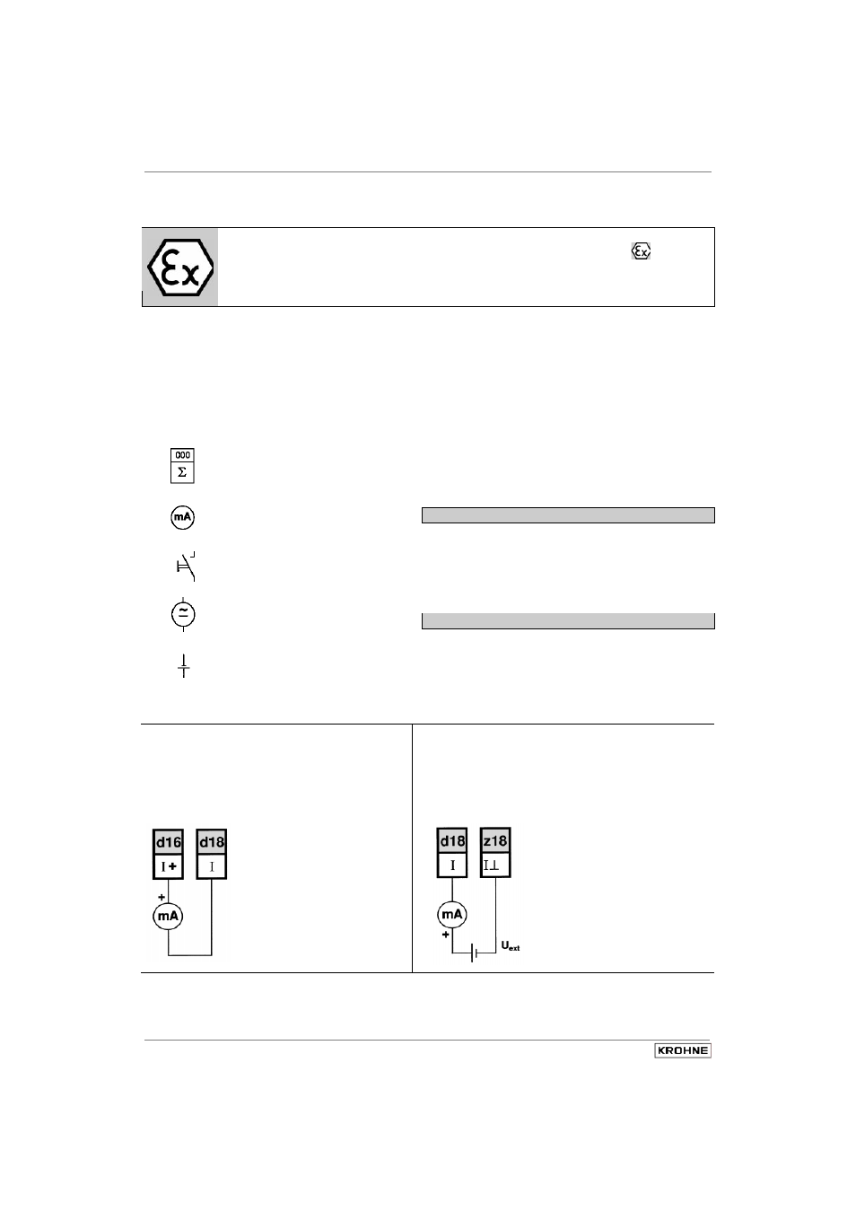
Active mode
Power for operation (activation) of outputs and
inputs supplied by the current output.
Passive mode
I
P
B1, B2
Current output (included HART
®
)
Pulse output
Status output (S) and / or
Control input (C)
Totalizer
- electromechanical (EMC)
- electronic (EC)
milliammeter
0-20 mA or 4-20 mA and other
Key, N/O contact
External voltage source (U
ext
),
DC or AC voltage,
connection polarity arbitrary
DC voltage,
external power source (U
ext
),
note connection polarity
External power source required for operation
(activation) of outputs and inputs.
c
Current output I
aktiv
d
Current output I
passiv
U = 0/4-20 mA
U
ext
15-22 V DC
22-32 V DC
R
L
< 800
Ω
R
L
0-500
Ω
0-800
Ω
I = 0/4-20 mA