KEPCO RTW 300W User Manual
Page 9
RTW 300W 101212
7
4.1
VOLTAGE ADJUSTMENT
Output voltage can be manually adjusted with the voltage adjustment control, Vadj (see Figure 4).
To adjust voltage, first place the unit under an operating load, then monitor the (+)S and (–)S
Sense terminals with a precision voltmeter and turn the voltage control to the desired operating
value (turn clockwise to increase voltage). Refer to Table 1 for the recommended Adjustment
Range of all the RTW 300W Models
4.2
REMOTE VOLTAGE CONTROL
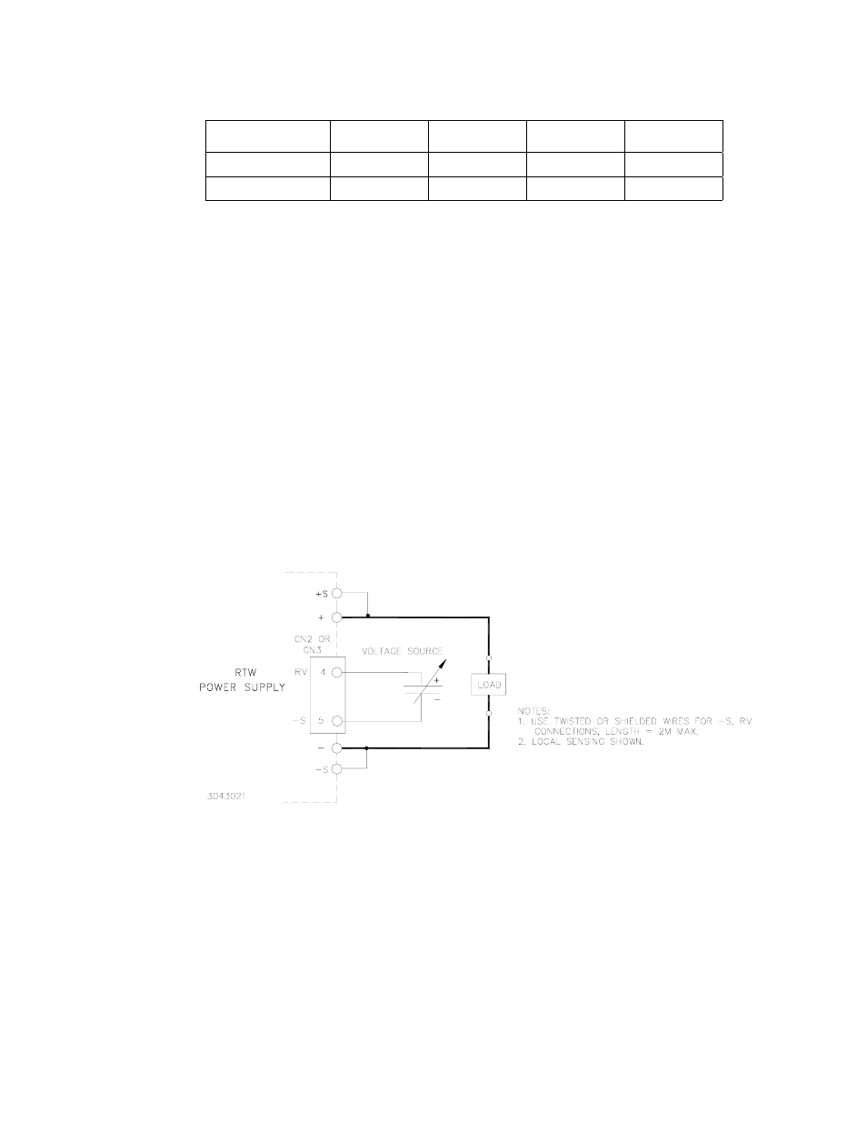
Output voltage can be adjusted by an external voltage source using the Output Voltage External
Adjustment function (RV) of connector CN2 or CN3. An RV voltage of approx. 5V can produce the
rated output voltage. First monitor the ±S terminals and use the Vadj control to establish the mini-
mum output voltage desired (output voltage decreases when trimmer Vadj is turned counterclock-
wise). Then connect the external voltage source across the RV and –S pins of CN2 or CN3 as
shown in Figure 5, using either twisted or shielded wires not more than 2 meters in length.
Optional Cable Kit 219-0493 (PAR. 6.6) may facilitate connections. Specifications are met when
voltage is within adjustment range shown in Table 1.
FIGURE 5. CONNECTIONS FOR REMOTE VOLTAGE CONTROL
4.3
REMOTE TURN ON-TURN OFF
When input source power is ON, the output may be turned ON or OFF with the remote control fea-
ture using the ±RC pins of connector CN2 or CN3 (see Figure 4). These pins accept a logic level
(2.4V to 24V “high” and 0.0 to 0.4V “low”), or a contact closure. When the ±RC pins are open,
using either a mechanical switch or a high level logic signal, the RTW 300W output is cut OFF.
When the RC pins are shorted or at a low logic level, the output returns to within specifications. At
low level logic, the maximum source current is 1.6mA and at high level the maximum sink current
is 1.0mA. The RC pins must remain shorted if remote ON-OFF is not used; use the shorting con-
nector provided with the unit. Optional Cable Kit 219-0493 (PAR. 6.6) may facilitate connections.
TABLE 4. MATING CONNECTORS
Connector
Number
Connector
Part Number
Socket Housing
Part Number
Contact
Part Number
MFR
CN1 B2B-XH-2
XHP-2
SXH-001T-P0.6
JST(1)
CN2, CN3
B5B-XH-2
XHP-5
SXH-001T-P0.6
JST(1)
(1) JST= Japan Solderless Terminal Mfg. Co.