KEPCO RTW 300W User Manual
Page 13
RTW 300W 101212
11
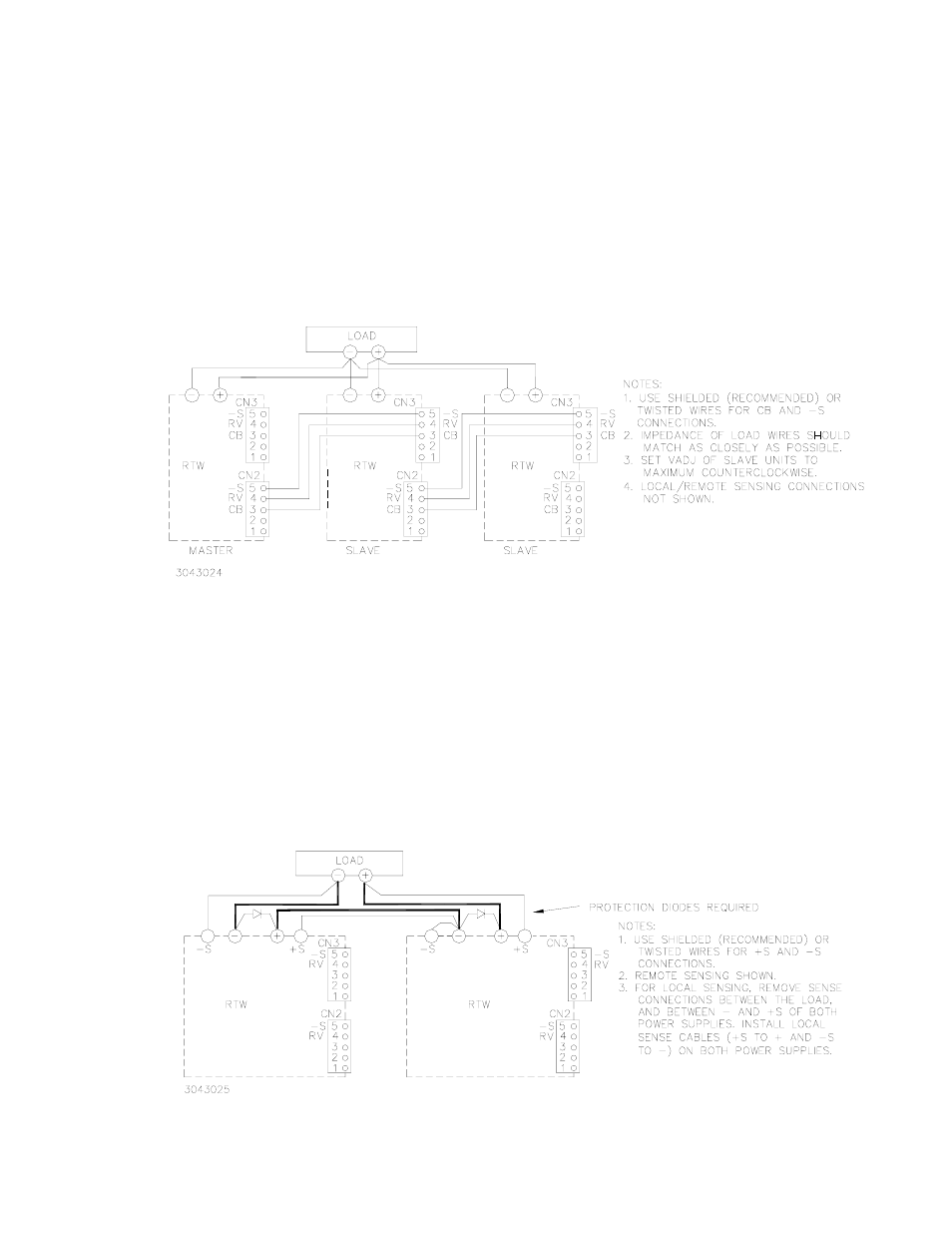
6.3.2.2 MASTER-SLAVE, SINGLE LOAD
Figure 10 shows the connection of three power supplies in parallel to a single load. The output
voltage of all power supplies is controlled by Vadj of the master. Current balancing is implemented
to equalize the load current (see PAR. 6.3.1). Vadj control of all slave units must be set to maxi-
mum counterclockwise for this configuration to operate properly. NOTE: Use shielded wire (rec-
ommended) or twisted wires for connections to RV and –S terminals. Match impedance of load
wires between each power supply and load by using the same wire lengths and wire sizes.
Optional Cable Kit 219-0497 (PAR. 6.6) may facilitate connections.
FIGURE 10. PARALLEL CONNECTION, MASTER-SLAVE, SINGLE LOAD
6.4
SERIES CONNECTION
Units may be connected in series to obtain higher voltages. When a number of power supplies are
operating in series, the current rating is to be limited to the rating of the power supply with the low-
est rating. Each Power Supply in series should be protected by a diode connected in parallel with
the output as shown in Figure 11. The diode protects against reverse voltages. It should be rated
for typically, V
REVERSE
≥ 2 x ΣV
OUT
of the series connection, I
FORWARD
≥? 2 xI
OUT
of the series
connection. Optional Cable Kit 219-0497 (PAR. 6.6) may facilitate CN2/CN3 connections, how-
ever the wire at pin 3 (CB) must be cut.
FIGURE 11. SERIES CONNECTION