KEPCO RTW 300W User Manual
Page 3
RTW 300W 101212
1
1.
INTRODUCTION
1.1
SCOPE OF MANUAL
This Operator's Manual covers the installation and operation of the Kepco RTW 300W Series of
Switching Power Supplies. For service information, write directly to: Kepco Inc., 131-38 Sanford
Avenue, Flushing, New York, 11355, U.S.A. Please state Model Designation and Serial Number of
your RTW Power Supply. This information can be found on the nameplate of the unit.
1.2
DESCRIPTION
The Kepco RTW 300W Series consists of seven models of switching power supplies, each with a
single output as shown in Table 1. Units may be operated with a nominal 100V a-c to 240V a-c
(input voltage range 85 to 265 Va-c), 50-60 Hz (input frequency range 47-66Hz; units also operate
up to 440Hz although leakage current, power factor and efficiency specifications may not be met).
They will also operate on 110V to 370V d-c input. The RTW 300W Series employs a forward con-
verter operating at 140 KHz. Regulation is provided by pulse width modulation. A power stage
with a MOSFET on each side of the primary winding, operating in the forward mode provides a
smooth isolated d-c output. A thyristor circuit prevents excessive turn-on current surge. A boost
converter operating at about 90KHz provides Power Factor Correction (PFC). Overvoltage protec-
tion, an isolated remote TTL ON-OFF control, an LED “output voltage ON” light and an output volt-
age adjust trimmer are provided. RTW 300W are low-profile convection-cooled units,
manufactured on an aluminum frame. Models with suffix KC include a cover; for applications
where a cover is not needed, contact Kepco for further information.
2.
SPECIFICATIONS
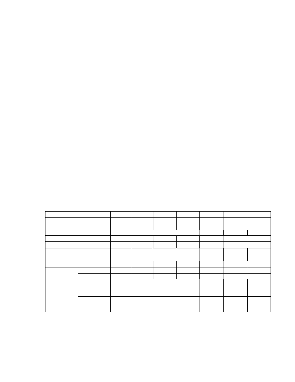
Table 1 contains specifications and operating limits of individual RTW 300W Series models. Table
2 contains specifications and operating limits common to all RTW 300W Series Models. These
specifications are at nominal input voltages at 25°C unless otherwise specified.
3.
INSTALLATION
Refer to Figures 1 and 3.
TABLE 1. OUTPUT RATINGS AND SPECIFICATIONS
MODEL RTW 300W
3.3-70KC
5-60KC
12-25KC
15-20KC
24-13KC
28-11KC
48-6.5KC
Output Volts d-c
3.3V
5V
12V
15V
24V
28V 48V
Adjustment Range (Volts)
1.8 - 3.6
3.5 - 5.6
7.2 - 14.4
10.5 - 18.0
16.8 - 26.4
19.6 - 33.6
33.6 - 55.0
Voltage Setting (Volts)
3.3 ±0.03
5 ±0.05
12 ±0.12
15 ±0.15
24 ±0.24
28 ±0.28
48 ±0.48
Maximum Output Rating (Watts)
231
300
300
300
312
308
312
Output Current (max.) (Amps)
(5)
70
60
25
20
13
11
6.5
Current Limit Setting (Amps)
(1)
73.5 - 84
63 - 72
26.3 - 30
21 - 24
13.7 - 15.6
11.5 - 13.2
6.8 - 7.8
Current Short Circuit (Amps)
87
78
36
29
25
17.5
11.5
OVP Setting (Volts)
(2)
4.0 - 4.6
6.2 - 7.0
14.8 - 16.8
18.6 - 21.0
29.8 - 33.6
34.7 - 39.2
55.5 - 59.9
Undervoltage
Protection
(4)
% Output
60
60
20
20
20
20
20
Time (Sec)
3
3
15
15
15
15
15
Efficiency
% typical
AC Input 100V
83
84
83
85
85
85
86
AC Input 200V
86
87
86
88
88
88
89
Ripple &
Noise
(3)
(mV, p-p)
Ripple
80
80
100
100
150
150
200
Ripple noise
120
120
150
150
200
200
300
Acceptable Output Capacitor (
µF)
(6)
10,000
10,000
10,000
10,000
10,000
10,000
10,000
(1) Square type.
(2) When overvoltage is detected, output is shut OFF. Recovery is by removing and reapplying power after about 30 seconds or by
opening and reclosing the ±RC pins of connector CN 2 or CN3
(3) Ripple and noise specifications are 1.5 times indicated values for temperature range of -10 to 0°C. Ripple and noise levels
above are satisfied when conditions are 0 to 100% load, 0 to 50°C (for 50 to 71°C see Figure 2), and bandwidth
≤ 100MHz.
(4) When output falls below rated output by the percent listed, for the time listed, output is shut OFF. Recovery is by removing and
reapplying power or by opening and reclosing the ±RC pins of connector CN 2 or CN3.
(5) Minimum output current is 0 Amps.
(6) Start-up time will change if this capacitor is added.