Table 2. output ratings and specifications – KEPCO HSF 300W Series (no suffix) Operator Manuals User Manual
Page 4
2
HSF 300W 050113
2.
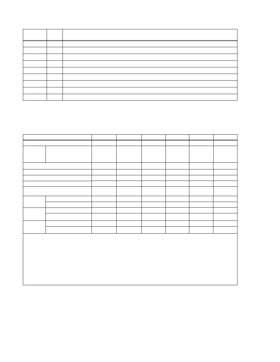
SPECIFICATIONS
Table 2 contains specifications and operating limits of individual HSF 300W Series models. Table
3 contains specifications and operating limits common to all HSF 300W Series Models. These
specifications are at nominal input voltages at 25°C unless otherwise specified.
+PF
16
+Power Fail of open-collector alarm circuit. Used with –PF, pin 19 (see PAR. 3.7.2.2).
CSB
17
Current Share Bus - Used whenever several power supplies are connected in parallel (see PAR. 5.).
RV
18
Remote Voltage - Used with REF, pin 15, for remotely controlling the output voltage (see PAR. 3.4.2)
–PF
19
–Power Fail of open-collector alarm circuit. Used with +PF, pin 16 (see PAR. 3.7.2.2).
+RC
20
+Remote On-off used with –RC, pin 21, to allow remote turn-on turn-off of the unit (see PAR. 3.5)
–RC
21
–Remote On-off used with +RC, pin 20, to allow remote turn-on turn-off of the unit (see PAR. 3.5)
GND
22
AC input ground
N
23
AC Input neutral
L
24
AC input line
TABLE 2. OUTPUT RATINGS AND SPECIFICATIONS
HSF MODEL
5-60
12-27
15-22
24-14
28-12
48-7
Output Volts d-c (nominal)
5
12
15
24
28
48
Output
Adjustment
Range
(1)
Using either front panel
trimpot, Voltage source or
external 5K ohm trimpot
(Volts d-c)
(2)
0 to 5.5
0 to 13.8
0 to 17.4
0 to 28.2
0 to 33
0 to 52.2
Output Current (nominal) (Amps)
60
27
22
14
12
7
Maximum Output Power (Watts)
(3)
300
300
300
300
300
300
Overcurrent Setting (Amps)
(4)
63-78
28.4-35.1
23.1-28.6
14.7-18.2
12.6-15.6
7.4-9.1
Short Circuit Current (Amps)
82
35
29
20
17
11
Overvoltage Protection (OVP)
(Volts d-c)
(5)
5.7 - 7.0
14.3 - 16.8
18.0 - 24.0
29.3 - 33.6
34.2 - 39.2
54.5 - 59.8
Efficiency
(% typ.)
AC Input 100V
72
74
75
78
78
79
AC Input 200V
78
78
79
82
82
83
Power Fac-
tor
(typ.)
AC Input 100V
0.99
0.99
0.99
0.99
0.99
0.99
AC Input 200V
0.95
0.95
0.95
0.95
0.95
0.95
Ripple &
Noise
(6)
(mV, p-p)
ripple 80
120
120
150
150
200
ripple noise
120
150
150
200
200
200
(1)
To adjust output voltage down to approximately 0V use external voltage source or resistance (see PAR. 3.4.2). Refer to Table
4 for minimum conditions required to maintain proper operation of alarm relay and visual LED indicator.
(2)
Using trimpot to attain voltages outside the specified adjustment range may trigger undervoltage (PAR 3.6.4) or overvoltage
(PAR 3.6.1) faults. Recovery is by removing, and after approximately 40 seconds, reapplying AC input power or by reset
(open and close) at ±RC terminals (no delay).
(3)
See Figure 2 for power derating.
(4)
Square type. Output voltage returns automatically only if cause is removed within 30 seconds (see PAR. 3.6.2).
(5)
When overvoltage is detected, output is shut OFF. Recovery is by removing, and after approximately 40 seconds, reapplying
AC input power or by reset (open and close) at ±RC terminals (no delay).
(6)
Ripple and noise levels above are satisfied when conditions are 0 to 100% load, 0 to 40°C (load is derated from 40 to 55°C,
see Figure 2), and bandwidth
≤ 100MHz.
TABLE 1. HSF REAR CONNECTOR PIN ASSIGNMENTS (CONTINUED)
Signal
Name
Pin
Function
- SN 488-B SN 488-D JQE 1/4 Rack Series KLP Series User Manual, Rev 2 KLP Series User Manual, Rev 4 KLP Series User Manual KFD 15-10-28W KFD 6-25-28W KFD 6-25-60W KFD 15-10-60W KFD 24-4.2-28W JQE Full Rack Series BHK-MG VISA Driver Manual (Both Full and 1/2 Rack) ABC VISA INSTRUMENT DRIVER ATE-DMG SERIES