4 undervoltage, 7 alarm settings, 1 visual alarm – KEPCO HSF 300W Series (no suffix) Operator Manuals User Manual
Page 12: 2 alarm signals, 1 internal isolated relay alarm, 2 optically-coupled logical alarm, R. 3.7.2.1), R. 3.7.2.2), Ar 3.6.4), R. 3.7.2)
10
HSF 300W 050113
OFF switch to OFF, waiting 40 seconds, then setting the POWER switch to ON. If fan rotation is
out of specification the power supply will not recover.
3.6.4 UNDERVOLTAGE
If power supply output voltage either falls below 80% of the programmed (set) value, or if output
voltage is programmed below the minimum values listed in Table 4, an alarm occurs if the internal
relay alarm (factory default, see PAR. 3.7.2.1) is enabled. To restart (reset) the unit, press and
release the OUTPUT RESET switch on the front panel or, if the remote on/off feature is in use
(see PAR. 3.5), open the connection between the RC pins and then reconnect the pins. The unit
may also be restarted by turning the POWER ON/OFF switch to OFF, waiting 40 seconds, then
setting the POWER switch to ON. To enable the alarm function when operating below the mini-
mum values listed in Table 4, refer to PAR. 3.7.2.2 to configure the optically-coupled alarm.
3.7
ALARM SETTINGS
3.7.1 VISUAL ALARM.
When the unit is connected in a parallel configuration, the front panel VDC ON/ALARM indicator
can be configured to light red if the respective power supply output voltage is lost or if the POWER
switch is set to OFF. This is enabled when DIP switch 1, position 8 set to ON. This can be useful
to indicate the loss of output voltage from one parallel-connected power supply that may not be
readily apparent. The visual alarm is normally disabled: DIP switch SW1, position 8 set to OFF
(factory default); requires minimums per Table 4 if enabled (see PAR 3.8).
3.7.2 ALARM SIGNALS.
Either of two options are available for signalling alarms: isolated relay contacts (factory default,
PAR. 3.7.2.1) or logic level alarm signals ±PF (PAR. 3.7.2.2). The ±PF logic level alarm option
must be used if the power supply is intended to operate below the minimum voltages listed in
3.7.2.1 INTERNAL ISOLATED RELAY ALARM
The first option, the factory default setting, uses an isolated internal relay offering normally closed
(NC) and normally open (NO) contacts referenced to an isolated common (AL COM). These con-
tacts may be used to configure “close on failure” or “open on failure” alarm circuits. (Refer to the
Series RA 19-4C Manual for alarm configurations for multiple HSF power supplies.) Setting posi-
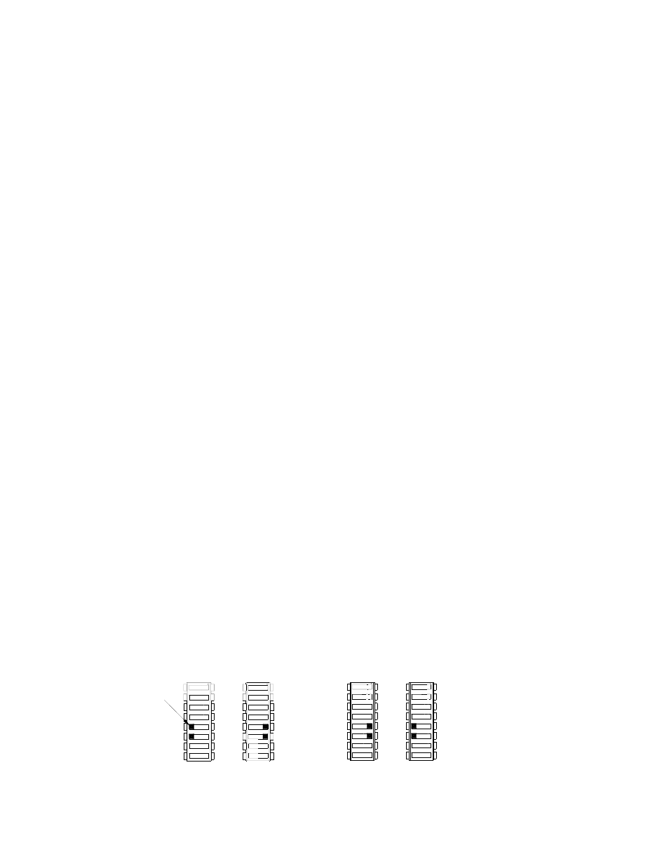
tions 5 and 6 of the DIP switches as shown in Figure 9A selects this option. The NC (pin 6 of the
rack adapter I/O connector) and NO (pin 7) signals are referenced to Alarm common (pin 14).
3.7.2.2 OPTICALLY-COUPLED LOGICAL ALARM
The second option uses optically-coupled logic level alarm signals, +PF (pin 5 of the rack adapter
I/O connector) and -PF (pin 13), provided directly from the Kepco RKW power supply that is the
heart of the HSF. This option is selected by setting positions 5 and 6 of the DIP switches as shown
in Figure 9B. Use this option if the power supply will operate below the minimum voltages speci-
fied in Table 4.
FIGURE 9. DIP SWITCH SETTINGS FOR OPTICALLY COUPLED LOGICAL ALARM
3042878
5
5 +PF
+PF 5
5
SW1
-PF 6
6
SW2
6
6 -PF
OFF
ON
OFF
ON
USE N.O. AND N.C CONTACTS
(FACTORY DEFAULT)
OF INTERNAL RELAY
A
LOGICAL ALARM
USE OPTICALLY-COUPLED
B
(+PF AND -PF)
5
6
6
SW1
5
SW2
OFF
ON
ON
OFF
+PF 5
-PF 6
6 -PF
5 +PF
TAB
- SN 488-B SN 488-D JQE 1/4 Rack Series KLP Series User Manual, Rev 2 KLP Series User Manual, Rev 4 KLP Series User Manual KFD 15-10-28W KFD 6-25-28W KFD 6-25-60W KFD 15-10-60W KFD 24-4.2-28W JQE Full Rack Series BHK-MG VISA Driver Manual (Both Full and 1/2 Rack) ABC VISA INSTRUMENT DRIVER ATE-DMG SERIES