Figure 7. connections for remote voltage control, 5 remote on-off, Dip switch settings for control of output voltage – KEPCO HSF 300W Series (no suffix) Operator Manuals User Manual
Page 10: Connections for remote voltage control, R. 3.5), 4 for minimum co, R. 3.5, E 6a, Re 6b. this remo, E 7. at the ra
8
HSF 300W 050113
NOTE:If remote voltage control is not implemented, the factory default for positions 1, 2 and 7 of DIP
switches SW1 and SW2 must be restored (Figure 6A).
FIGURE 6. DIP SWITCH SETTINGS FOR CONTROL OF OUTPUT VOLTAGE
It is possible that overvoltage protection may be triggered if the output voltage is decreased to a low
level very quickly when the power supply is at a low load condition.
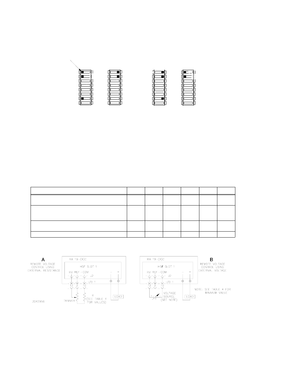
RESISTANCE: Connect the external trimmer as shown in Figure 7A. Suggested value for the trim-
mer control is 5K ohms. Referring to Figure 7A, Resistor R is used to obtain minimum output volt-
age required to ensure proper operation of the alarm relay and LED indicator; see Table 4 for
values. NOTE: Output voltage may not adjust to 0V due to residual trimmer resistance.
VOLTAGE. By adjusting an external 0 to 6V voltage source (0 to 5.5V for the 48V model), the HSF
power supply output voltage can be adjusted as specified in Table 2. To ensure proper operation of
the alarm relay, meter and LED indicators, do not adjust external voltage below minimum listed in
Table 4. Connect the voltage source across the RV and –COM pins as shown in Figure 7B.
FIGURE 7. CONNECTIONS FOR REMOTE VOLTAGE CONTROL
3.5
REMOTE ON-OFF
When power is ON at the source, the output may be turned ON or OFF using the ±RC signals if
the remote ON-OFF feature is enabled. Note that when remote ON-OFF is enabled, the RESET
OUTPUT switch does not function. Remote ON-OFF is enabled by setting DIP switch positions 3
and 4 as shown in Figure 8B. The +RC and –RC signals (at the rack adapter I/O connector, pins
15 and 8, respectively) then turn the unit on or off. These pins accept a logic level (2.4V to 24V
TABLE 4. MINIMUM CONDITIONS FOR RELAY, METER AND LED OPERATION
HSF MODEL
5-60
(2)
12-27
15-22
24-14
28-12
48-7
Minimum HSF output voltage required for continuous
relay and LED functioning (Volts d-c)
4.0
5.5
6.5
6.5
6.5
6.5
Minimum resistance of Limit resistor R (Figure 7A) in
series with 5K ohm Trimpot to ensure proper operation
of LEDs and relay (Ohms).
(1)
5K
1.9K
1.8K
1.1K
930
610
Minimum external voltage (Figure 7B) to ensure proper
operation of LEDs, meter and relay. (Volts d-c).
(1)
4.0
2.2
2.16
1.35
1.16
0.67
Voltage source range (Volts d-c)
0 - 6
0 - 6
0 - 6
0 - 6
0 - 6
0 - 5.5
(1) - If operating below minimums listed, see PAR. 3.7.2.2 to implement ±PF alarm signals to monitor power supply status.
(2) -LED brightness of HSF 5-60 is dimmer than other models. This is normal.
OFF
SW1
3043279
COM 7
REF 1
RV 2
7
SW2
1
ON
2
1
2
OFF
1 REF
2 RV
ON
SW1
SW2
7
1
2
OFF
ON
1
2
OFF
ON
USING Vadj CONTROL
FRONT PANEL VOLTAGE CONTROL
A
B
(FACTORY DEFAULT)
REMOTE VOLTAGE CONTROL
OR VOLTAGE SOURCE
USING EXTERNAL TRIMPOT
COM 7
REF 1
RV 2
2 RV
1 REF
TAB
- SN 488-B SN 488-D JQE 1/4 Rack Series KLP Series User Manual, Rev 2 KLP Series User Manual, Rev 4 KLP Series User Manual KFD 15-10-28W KFD 6-25-28W KFD 6-25-60W KFD 15-10-60W KFD 24-4.2-28W JQE Full Rack Series BHK-MG VISA Driver Manual (Both Full and 1/2 Rack) ABC VISA INSTRUMENT DRIVER ATE-DMG SERIES