In-Situ Well Cap Cable Holder User Manual
Well cap cable holder
(toll-free, US and Canada) or 970 498 1500
www.in-situ.com
Information is subject to change without notice. In-Situ and the In-Situ logo, Win-Situ, TROLL, BaroTROLL, RuggedReader, and RuggedCable are trademarks or
registered trademarks of In-Situ Inc. Copyright © 1997-2008. by In-Situ Inc. All rights reserved.
1 800 446 7488
Information Sheet
TROLL
®
Accessories
0011780 rev. 002 09/08
ApplicAtion
Liquid-tight strain-relief connector for the top of a well
physicAl Description
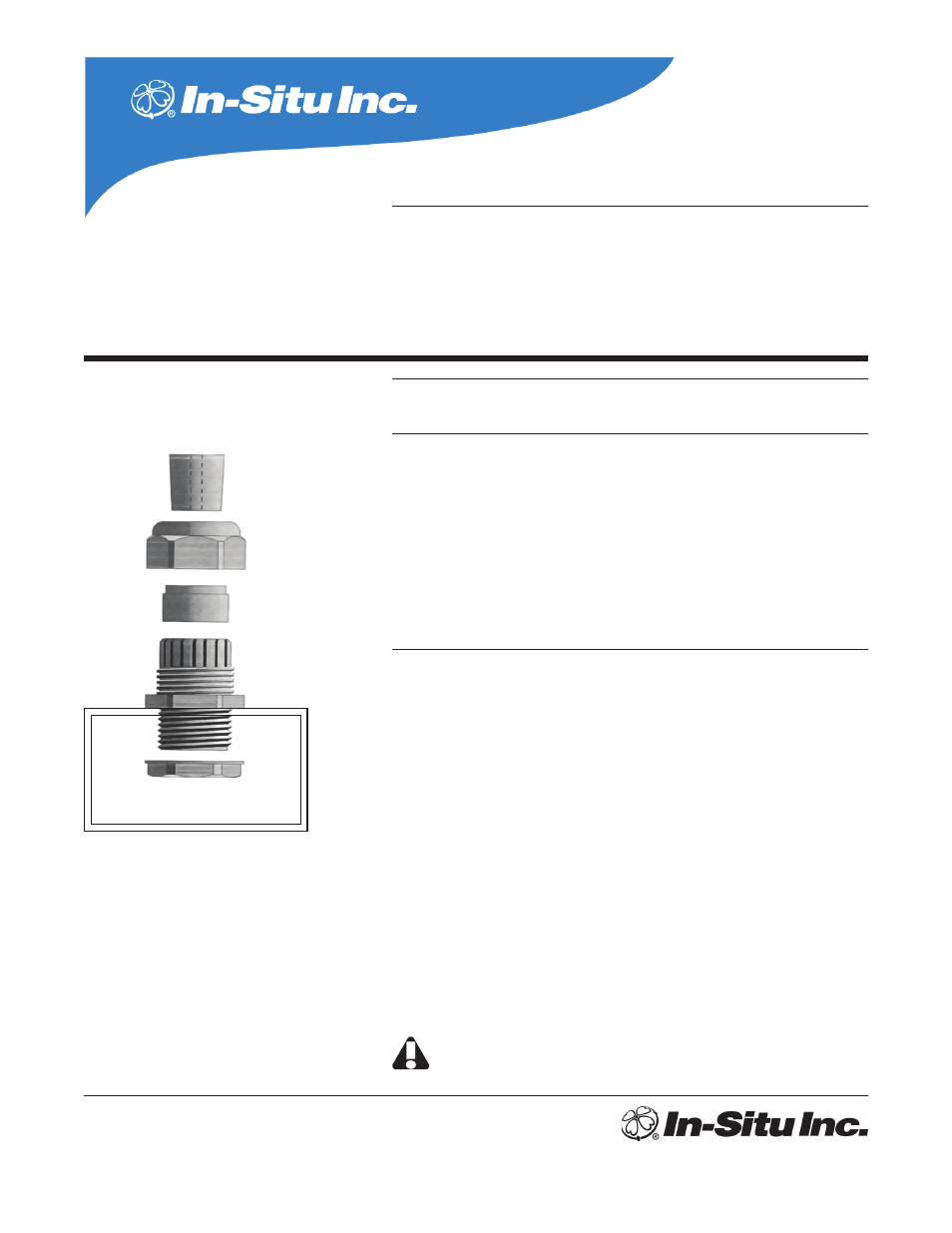
The connector consists of 5 pieces:
A. Rubber stopper with pre-drilled hole that is cut to wrap around cable
B. Dome nut, 2.75 in across
C. Rubber ring
D. Threaded section, 1.5 in NPT
E. Flat nut
Pressure rating: 60 psi max. at room temperature (20-25°C); 30 psi up to 50°C (122°F)
Dimensions: 2.75 in diameter at widest point, 1.5 in NPT
instAllAtion
1. Drill a 1.5 in hole in the well cap to accommodate the connector D.
2. Insert D into the hole, threaded side first.
3. Screw nut E to the threaded section underneath the well cap. Close the well cap.
4. Mark the cable at the point where you want it to enter the well. Note that you won’t be
able to move the transducer once it’s installed.
5. Put the transducer through dome nut B and pass the dome nut onto the cable.
6. Work rubber ring C over the transducer and pass it onto the cable.
7. Lower the transducer down the well through the well cap.
8. At the mark you made on the cable, open the cut in the rubber stopper and insert the
cable. The small end of the stopper should be facing the transducer.
9. Work the rubber ring into the unthreaded part of section D until it is resting on the ridge.
10. Force the rubber stopper as far into the dome nut as possible. It helps to wet it.
11. Screw down the dome nut.
Do not use at pressures exceeding 60 psi. At higher pressure, the transducer or miniTROLL
may be forcibly ejected from the fitting.
Well cap cable holder
Catalog No. 18090
A
B
C
D
E
Well cap