Accessing the data center, Maintenance – In-Situ TROLL Link 101 and 201 Quick Start Guide User Manual
Page 2
Information subject to change without notice. In-Situ, In-Situ logo, BaroMerge, BaroTROLL, HERMIT, iSitu, Pocket-Situ, RDO, RuggedCable, RuggedReader, TROLL, and Win-Situ are trademarks or registered trademarks of In-Situ Inc.
©
2013. All rights reserved.
Installing a 10 or 20 W Solar Panel and External
Battery Kit
Please refer to the TROLL Link Manual for instructions on
installing a 10 or 20 W Solar Panel and External Battery
Kit.
Installing a Battery
1. Install batteries with the terminals oriented toward the
top of the enclosure.
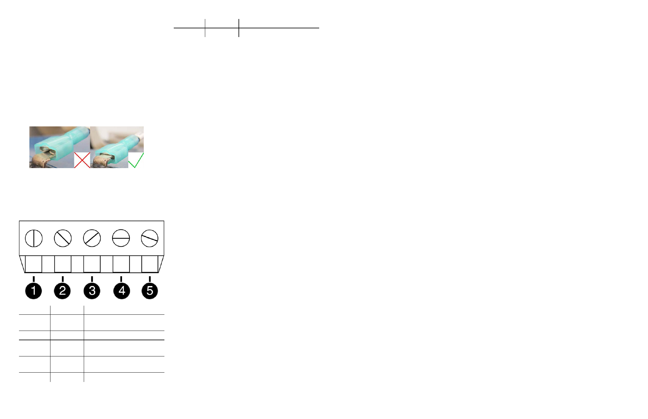
2. Plug the black (negative) leads into the black terminals of
the batteries first. Ensure that the terminal does not sit
between the lead clip and the plastic sheath, but that the
lead clip encompasses the battery terminal.
3. Plug the red (positive) leads into the red battery
terminals. Ensure that the terminal does not sit between
the lead clip and the plastic sheath, but that the lead clip
encompasses the battery terminal.
TROLL Link 101 and 201 Wiring Diagram
Number
Function
Wire
1
DC Com
(-)
Bulkhead black wire; solar
panel black wire
2
RS485 (-)
Bulkhead green wire
3
RS485
ground
4
RS485
(+)
Bulkhead blue wire
5
DC (+)
Bulkhead red wire; fuse blue
Number
Function
Wire
wire
Accessing the Data Center
Note that it may take up to an hour for data to be
transmitted to the Data Center, depending on the data
service package you have.
1. Open a Web browser.
2. Enter the URL:
http://www.isi-data.com
3. Enter your User ID and Password supplied by In-Situ.
Click Login.
4. The Site Index appears. The Site Index displays the site
name, most recent message received date, number of
devices at the site, and the alarm status.
5. Click a site name to view more data from that site.
6. Select a Device to view more data from that device.
If the next transmission interval has not occurred,
you should confirm that communication from all
devices in the network has been successful.
1. Ensure all components of the TROLL Link Telemetry
System have power applied.
2. From the Site Index, click the site name.
3. Click the first device listed.
4. Select Manage Device under the Site Management
heading in the left navigation bar.
5. Select View Config Messages under the Device
Config heading in the left navigation bar.
If data does not refresh at the expected rate or the site
does not display the network, contact technical support.
Maintenance
Fuse Replacement
Two fuses are located on the left edge inside of the
enclosure. The left fuse connects to the internal battery,
the right fuse connects to the charger/external power. The
fuses are 2 amp, time-delay, speed-type fuses rated for
250 VAC. Replace as needed.
Enclosure Desiccant
It is extremely important to use a properly-sized
desiccant for your deployment, and to change desiccant
before the entire volume has turned pink. Use
enough desiccant to effectively keep electronics dry until
your next scheduled maintenance. Desiccant life span is
dependent on site conditions.
The enclosure contains one tube of desiccant that absorbs
moisture as it enters the enclosure through the vent tube.
Keep the vent tube clear of obstructions. Replace as
needed. An additional desiccant pack may be located at
the top of the enclosure. Replace or dry as needed.
Cleaning
Clean the outside of the enclosure with a soft, damp cloth.
Do not use ammonia or other harsh chemicals.