GW Instek GDM-452 User Manual
Page 2
1. Set to the maximum range and reduce it gradually if the measured
current is unknown.
2. If "1" displays on LCD, it indicates over-range, please select a higher
range for your measurement.
3. “ ” indicates the maximum input current. mA input is protected by
200mA/250V fuse; 10A/250V fuse is used to protect 10A range.
1. Set to the maximum range and reduce it gradually if the measured
voltage is unknown.
2. If "1" displays on LCD, it indicates over-range, please select a higher
range for your measurement.
3. “ ” indicates not to input voltage higher than 1000V, which may
cause damage to the Multimeter or personal injury although the reading
may be obtained.
4. Extreme care should be taken to avoid electric shock when measuring
high voltage.
P/N:82DM-45200M01
Ⅴ.
Making Measurements
Ⅵ.
Maintenance
Ⅶ.
Replacing the Battery
Ⅷ.
Accessories
DC Current
Measuring AC Current
Data Hold
Auto Power Off
Measuring Resistance
Measuring Capacitance
Measuring Frequency
Testing Diodes and Continuity
Measuring AC Voltage
Measuring DC Current
(1) Power on the Multimeter and inspect 9V battery. Replace the battery
if “ ” displays. If not, proceed into next step.
(2) Pay attention to rated voltage or current value next to “ ” near
input terminals, any input that go beyond the rating may damage the
Multimeter.
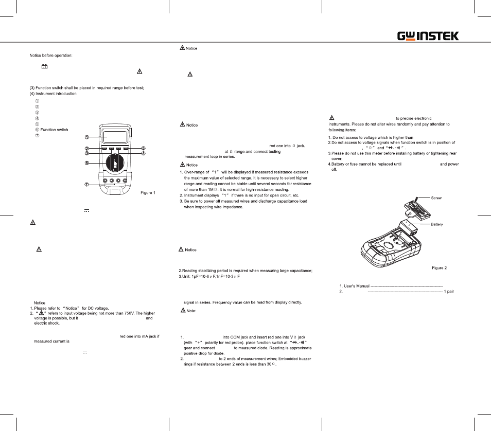
LCD display
POWER button
AC+DC button
HOLD button
CANCEL AUTO POWER OFF button
Input jack
1. Insert test leads into input jacks(Red to V and black to COM).
2. Set the function switch to V range; Connect test leads to the wire
under test in parallel, and the positive polarity of the test end will indicate.
Notice
1. Insert black test lead into COM jack and insert red one into V jack;
2. Place function switch at V~ range scope and then connect test leads
to measurement wires in parallel.
may cause damage to internal wires
1. Insert black test lead into COM jack and insert
not more than 200mA. Insert the red test lead into
10A jack if measured current is between 200mA and 10A.
2. Place function switch at A range and then connect testing leads
to measurement loop in series. It will dispaly current and polarity of
red test lead at the same time.
1. Insert black test lead into COM jack and insert red one into mA jack if
measured current is not more than 200mA. insert red test lead into
10A jack if measured current is between 200mA and 10A.
2. Place function switch at A~ range and connect testing leads to
measurement loop in series.
1. Please refer to “Notice” for DC current measurement.
1. Insert black test lead into COM jack and insert
2. Place function switch
leads to
1. Insert the tested capacitor directly into capacitance jacks(without need
of test leads).
2. The floating reading exists every time you switch to another
capacitance range and reset to zero before connecting to a tested
capacitor, which however will have no impact on the accuracy.
1. Discharge the tested capacitor before measurement, although the
capacitance ranges are protected internally, it may also cause damage
to the multimeter.
1. Insert red test leads into HZ jack and insert black one into COM jack;
2. Place function switch at kHZ range and connect test leads to frequency
The accuracy cannot be ensured if input signal voltage is higher than
30Vrms, and please take extreme care.
Insert black test lead
test leads
Connect test leads
1. Press HOLD button to realize such function;
2. Whether the test leads are disconnected or not will not influence Data
Hold function.
1. The Multimeter is designed with automatic power-off circuit to power
off after instrument operates for about 15 minutes and enter into
sleeping status;
2. Press POWER button twice to wake up the Multimeter from the sleep
mode.
This kind of Multimeter belongs
1000VDC or 750Vrms AC.
“current ranges”
removing test leads
1 pc
Test Leads
This manual contains proprietary information, which is protected by copyright. All
rights are reserved. No part of this manual may be photocopied, reproduced or
translated to another language without prior written consent of Good Will company.
The information in this manual was correct at the time of printing. However, Good Will
continues to improve products and reserves the rights to change specification,
equipment, and maintenance procedures at any time without notice.
Good Will Instrument Co., Ltd.
No. 7-1, Jhongsing Rd., Tucheng Dist., New Taipei City 236, Taiwan