GW Instek GFG-8200A Series User Manual
Page 12
FUNCTION GENERATOR-SERIES
INSTRUCTION MANUAL
21
5-8.AM/FM operation
(1) Select function
8
first; then select Range
7
, rotate FREQ
13
to set
required frequency range.
(2) Connect output terminal
22
to oscilloscope for observing output
signal.
(3) Press MOD
15
and pull out (press) MOD
16
to obtain FM/AM
modulation mode.
(4) Adjust MOD
16
to achieve required modulation ratio.
5-9. Precaution item
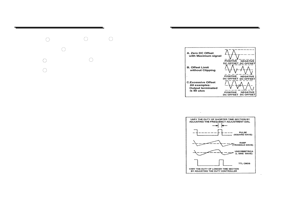
(1) Adjust DC OFFSET, will provide to change voltage of ±10V (no load)
or ±5V (50Ω load). However, signal added DC level, is still
limited to ±20V (no load) or ± 10V (50Ω load). In case of over-
voltage, clip will appear as shown in Figure 2:
(2) Output connector label 50Ω, indicated that signal source impedance is
50Ω. Connect to any of impedance circuit, but output voltage and
terminal impedance will be rated. To avoid oscillation, terminal shall
be connected to 50Ω (When using high frequency and square output),
and its connecting line shall be as short as possible.
(3) When adjust Duty knob to leftward position, the ratio of positive state
to negative state, expand to not less than 80:20. It can expand Square
wave to Pulse wave, expand Triangle wave to Ramp wave and Sine
wave to unsymmetrical Sine wave. As shown in Figure 3 is for
adjustment of Duty control to obtain required waveform.
FUNCTION GENERATOR-SERIES
INSTRUCTION MANUAL
22
z Figure 2.
z Figure 3.