Installation, Figure 1 dimensional overview, 0 installation – Detcon 1600-N1P-RD User Manual
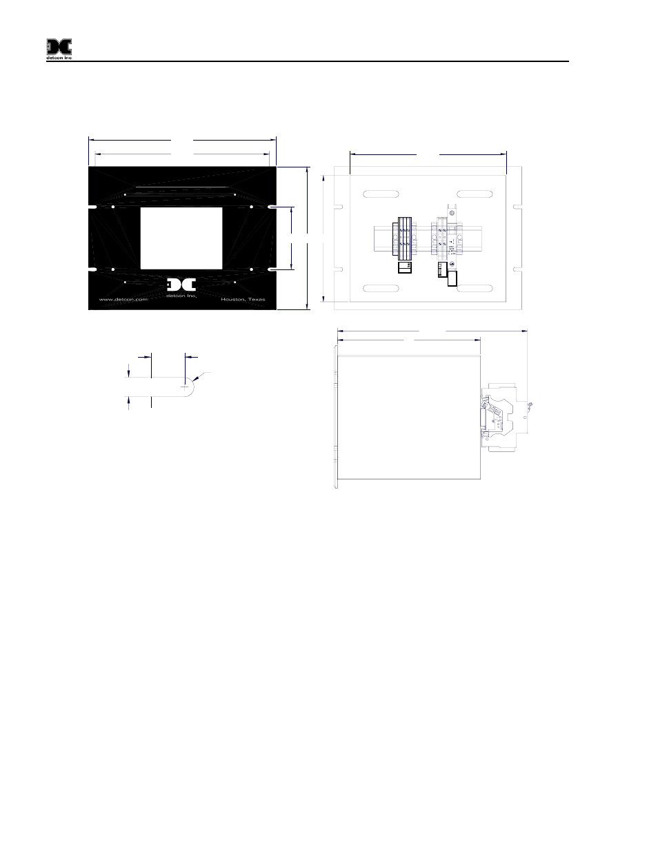
Page 6: Front view, Slot detail back view side view
1600/6400-N1P-RD
3.0 Installation
Securely mount the Model 1600/6400-RD enclosure
8.75"
8"
10.63"
Model 6400-N1P-RD
Multi-Channel Gas Detection Control System
10.5"
9.75"
8" 7.1"
3.5"
G
round
24VD
C
2A
A
B
RS-485
O
I
Front View
0.375
0.218
R0.109
Slot Detail
Back View
Side View
Figure 1 Dimensional Overview
Connect 110/220VAC input wiring to the terminals labeled “VAC (L1)”, “Neutral (L2)”, and “Ground” (See
Figure 2). For 220Volt Units connect L1 to the terminal labeled “VAC (L1)”, L2 to the terminal labeled
“Neutral (L2)” and Ground to the terminal labeled “Ground”. The Power Supply is capable of handling AC
inputs from 100-240VAC 50-60Hz with no degradation.
Connect the RS-485 wiring from The 6400 Control Unit to the terminals located on the Back Panel. These
terminals are labeled “A” (+), “B” (–), and “Shld” (shield) for primary RS-485 communication (Figure 2).
RS-485 wiring should consist of a two conductor, shielded twisted pair (Belden P/N 9841).
1600/6400-N1P-RD- Instruction Manual Rev. 1.0
Page 2 of 14