Modbus™ addressing of sensor inputs, Figure 5 set # active channels and relays, Figure 6 addressing gas channels – Detcon 1600-N1P-RD User Manual
Page 10
1600/6400-N1P-RD
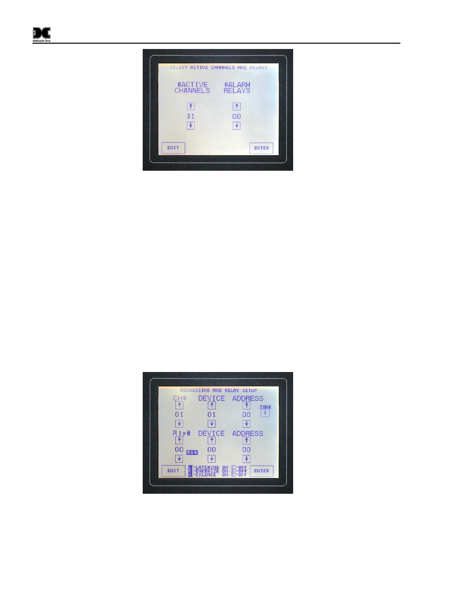
Figure 5 Set # Active Channels and Relays
Use the up and down arrows to make selections. Press ‘ENTER’ after the appropriate selections for # active
gas channels and relay outputs have been made.
The number of alarm relays should not be set in the Remote Display, as they have no function.
5.3.2 Modbus™ Addressing of Sensor Inputs
Addressing Gas Channels with DA-4 Modules
This function is used to identify the “device” and “address” of gas sensor inputs using the DA-4 Module. Each
gas channel will need to have the Channel #, Device, Zone and Address set and must match the configuration
entered in the 1600/6400 Controller.
Use the up, down arrows to increment and decrement the entries. Press ‘ENTER’ after each new CH # entry is
made. The ‘Zone’ key increases in number as the ‘Zone’ key is pressed. When the maximum zone number is
reached, the ‘Zone’ key will start back at zone one and continue to advance with every key press. Do not wait
until all entries are made before hitting the ‘ENTER’ key to accept the inputs. It is best to enter a sensor and
enter the data before going on to the next sensor.
Figure 6 Addressing Gas Channels
Addressing Serial Sensors
This function is used to identify the “device” and “address” of serial sensor inputs. Each gas channel will need
to have the Channel #, Device, Zone and Address set and must match the configuration entered in the
1600/6400 Controller.
1600/6400-N1P-RD- Instruction Manual Rev. 1.0
Page 6 of 14