3 battery backup - auxiliary 24vdc input, 4 initial power checks, Battery backup - auxiliary 24vdc input – Detcon 880S-N1R User Manual
Page 15: Initial power checks, Figure 15 typical 24vdc input connections
880-N1R
880-N1R Instruction Manual
Rev. 0.0
Page 11 of 38
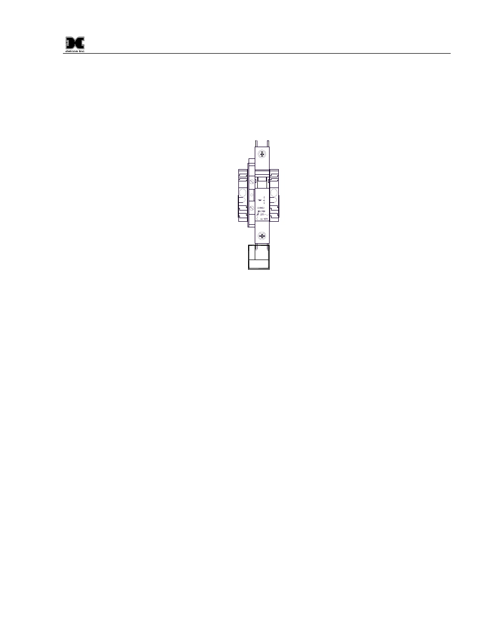
6. If applicable, connect a 24VDC Battery Backup or Auxiliary 24V source to the terminal blocks
labeled “24VDC INPUT” (24V+ and 24V–) (Figure 15).
NOTE: This input should be capable of supplying at least 5Amps at 24VDC in order for the unit to
operate properly. Insufficient current capabilities may cause detrimental damage to the unit and will
void the warranty.
O
I
5A
24V +
24V -
24VDC
INPUT
Part of
TB1
4
5
Figure 15 Typical 24VDC Input Connections
3.3 Battery Backup - Auxiliary 24VDC Input
If an Auxiliary 24VDC Input is connected to the unit, the input voltage may need to be adjusted to insure
proper operation. If the 24VDC input is being used to operate the unit, the source must be able to provide at
least 5Amps to insure proper unit operation. The unit utilizes a 5A Circuit Breaker to provide over current
protection. Measure the voltage between TB1-4 and TB1-5. This voltage should read above 21.6VDC and
below 26VDC.
If the 24VDC input is to be used as a Backup or Auxiliary 24VDC Input, adjustments may be required to
insure that this 24VDC Input is below the internal power supply voltage. To accomplish this turn “OFF” the
24VDC Input Circuit Breaker (located at TB1-5) measure the voltage between TB1-9 and TB1-10 (refer to
Figure 6 and Figure 10), this reading should be the power supply voltage. If the voltage measured across the
Power Supply is lower than the Auxiliary 24VDC Input (as measured between TB1-4 and TB1-5), the internal
power supply will not be used to supply power to the unit. The Auxiliary 24VDC Input to the unit should be
adjusted to at least 0.1-0.15VDC below the unit’s 24V Power Supply (as measured across TB1-9 and TB1-10)
for correct operation. This will insure that the unit does not operate on the Auxiliary 24VDC Input unless the
AC power is lost. Once the Auxiliary Input 24VDC is properly adjusted, turn the 24VDC Input Circuit
Breaker “ON”.
3.4 Initial Power Checks
Upon completion of all field wiring, apply power to the 880 by setting both the AC Circuit Breakers and DC
Circuit Breakers to “ON” and pushing the “POWER ON/OFF” switch on the front panel. The “POWER”
LED should illuminate. If all connections have been made properly, the “FAULT” and “ALARM” LED’s
should not be illuminated. The unit will go through a brief initialization and display the “Main Screen”
(Figure 28, Section 4.3). The “AC” box on the display should be green showing that AC is attached to the
unit. The “USB” box should be gray to indicate that no USB drive is attached.