2 unit connections, Unit connections, Figure 8 installing din-rail mounted modules – Detcon 880S-N1R User Manual
Page 12: Figure 9 setting device addresses, I/o module addressing, Serial connections
880-N1R
880-N1R Instruction Manual
Rev. 0.0
Page 8 of 38
RELAY
COMM
M
S
D
L
S
D
4-20mA
INPUT
COMM
M
S
D
L
S
D
4-20mA
INPUT
COMM
M
S
D
L
S
D
4-20mA
INPUT
COMM
M
S
D
L
S
D
4-20mA
INPUT
COMM
M
S
D
L
S
D
RELAY
COMM
M
S
D
L
S
D
RELAY
COMM
M
S
D
L
S
D
RELAY
COMM
M
S
D
L
S
D
SBA
-
+
S
B
A
-
+
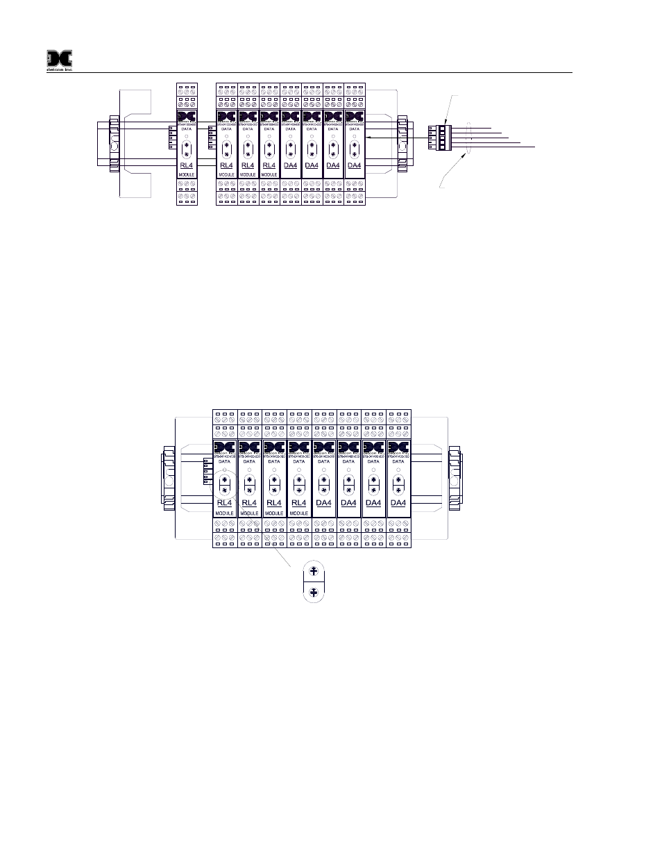
RS-485 I/O Connector
RS-485 and Power
(Beldon Cable P/N 1502P)
Figure 8 installing Din-Rail mounted modules
I/O Module Addressing
I/O modules must be serially addressed to establish correct communications. All Modules are addressed in
Hexadecimal. Typically, the modules will be addressed from 01 to FF Hex starting from the module on the
right hand side of the stack. The I/O module’s address is established by setting the two rotary switches to the
correspondingly correct position. The top rotary switch sets the Most Significant Bit (MSB). The bottom
rotary switch sets the Least Significant Bit (LSB). For an address of 01, set the top switch (MSB) to 0 and the
bottom switch (LSB) to 1. See Appendix B for Decimal to Hexadecimal conversion.
NOTE: All addresses must be unique. There can be no duplication of addresses or a Communication
Error (NO COMM) will occur.
RELAY
COMM
M
S
D
L
S
D
4-20mA
INPUT
COMM
M
S
D
L
S
D
4-20mA
INPUT
COMM
M
S
D
L
S
D
4-20mA
INPUT
COMM
M
S
D
L
S
D
4-20mA
INPUT
COMM
M
S
D
L
S
D
RELAY
COMM
M
S
D
L
S
D
RELAY
COMM
M
S
D
L
S
D
RELAY
COMM
M
S
D
L
S
D
M
S
B
L
S
B
0
12
3
4
5
678
9A
B
C
D
EF
0
12
3
4
5
678
9A
B
C
D
EF
Figure 9 Setting Device Addresses
3.2 Unit Connections
Connections to the 880 are made via terminals on TB1, located on the back of the unit, refer to Figure 6.
Serial Connections
1. For Serial Units (880S), connect the RS-485 Modbus™ network to the terminal blocks labeled
“Primary RS-485,” “A,” “B,” and “Shld” (Figure 10). Ensure that the network is properly laid out.
Proper layout of the RS-485 network is important for correct operation. Refer to Appendix A (RS-485
Integration and Wiring) for proper network layouts. The unit provides no power for external serial
devices connected to the unit.