Figure 12 typical rl4 module, Figure 13 main 880 terminal blocks and connections, Figure 14 typical input power connections – Detcon 880S-N1R User Manual
Page 14
880-N1R
880-N1R Instruction Manual
Rev. 0.0
Page 10 of 38
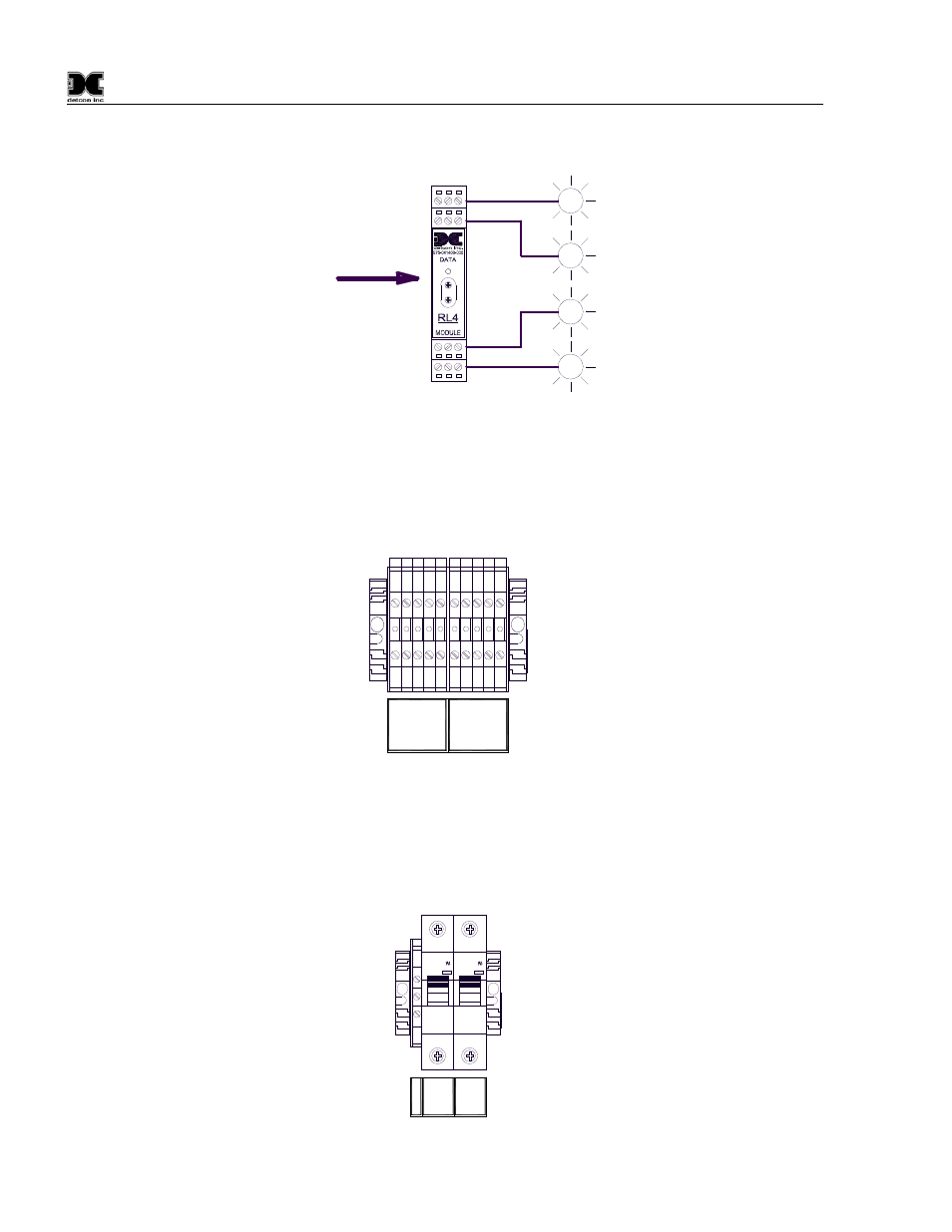
are provided on each RL4 module for associated annunciators. These connections consist of a set of
terminals (Common, Normally Open, Normally Closed) for the associated relay.
RELAY
COMM
M
S
D
L
S
D
A
A
A
A
ALARM 1
ALARM 2
ALARM 3
FAULT
M
S
D
L
S
D
RS-485 from 880
Figure 12 Typical RL4 Module
4. Terminal blocks are provided for connection to other external devices such as a remote display, a
printer, or other device capable of communication with the 880. The Remote display should be
connected to the “REMOTE OUTPUT” terminal blocks, and other devices should be connected to the
“RS-422 SLAVE” terminal blocks.
TXD+
TX
D
-
RX
D+
REMOTE
OUTPUT
RX
D-
0V
TXD+
TX
D
-
RX
D+
RS-422
SLAVE
RX
D-
0V
11 12 13 14 15 16 17 18 19 20
Part of
TB1
Figure 13 Main 880 terminal blocks and connections
5. Connect 110-220VAC input to the Fuse Block labeled “VAC (L1)” in the lower left of the enclosure.
Connect Neutral (or L2) to terminal labeled “NEU (L2)” and Ground to the Green/Yellow terminal
labeled “GROUND” (Figure 14). The power supply is able to accept AC input voltages from 100 to
240 volts at 50 or 60Hz.
I ON
C3
WMS1C03
240V-
10000
I ON
C3
WMS1C03
240V-
10000
1
2
3
Ground
VAC
(
L
1
)
NE
U
(L2
)
Part of
TB1
Figure 14 Typical Input Power connections