Figure 5 remote rs-422 connections, Figure 6 remote interconnect wiring, Figure 7 typical input power connections – Detcon 880RS-N4X User Manual
Page 8
880R-N4X
880R-N4X Instruction Manual
Rev. 0.1
Page 4 of 18
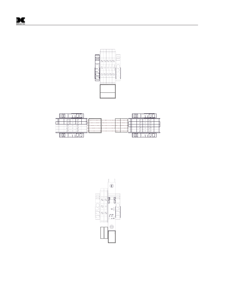
4. Connect the RS-422 Serial communications cable to the input terminal blocks inside the 880 Remote
Display labeled “TERMINAL INPUT” as shown in (Figure 5).
TX
D
+
TXD
-
RX
D
+
TERMINAL
INPUT
RXD
-
0V
Figure 5 Remote RS-422 connections
0V
RXD-
REMOTE DISPLAY
RXD+
TXD+
TXD-
CUSTOMER SUPPLIED
WIRING
TXD+
TXD-
RXD+
TERMINA
L
IN
PU
T
RXD-
0V
TXD+
TXD-
RXD+
REMOT
E
OUT
P
UT
RXD-
0V
MAIN 880
Figure 6 Remote Interconnect Wiring
5. Connect 110-220VAC input to the Fuse Block labeled “VAC (L1)” in the lower left of the enclosure.
Connect Neutral (or L2) to terminal labeled “NEU (L2)” and Ground to the Green/Yellow terminal
labeled “GROUND” (Figure 7). The power supply is able to accept AC input voltages from 100 to
240 volts at 50 or 60Hz.
O
I
1A
Gr
o
u
nd
VAC
(L
1)
NEU
(L2
)
Figure 7 Typical Input Power connections
Upon completion of all field wiring, apply power to the Main 880 and the 880 Remote Display. The unit will
go through a brief initialization and display the “Main Screen” (Figure 15). The “AC” box on the display
should be green to show that AC is attached to the unit. The “USB” box gray to indicate no USB drive is
attached.