0 system operation, 1 main screen – Detcon 880RS-N4X User Manual
Page 16
880R-N4X
880R-N4X Instruction Manual
Rev. 0.1
Page 12 of 18
5.0 System Operation
The touch screen display serves as the graphic user interface to the system. Maneuvering through the system
screens and accessing data fields is accomplished by touching the wand to the appropriate area, box, button, or
key on the screen. The provided “wand” should be the only instrument used to activate the screen as other
instruments may cause damage to the screen.
5.1 Main Screen
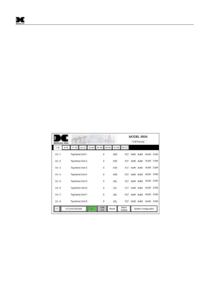
The main screen is the default screen of the unit (Figure 21). The screen displays the first 8 channels, channel
descriptions, current readings, gas type, and sensor status for each channel. If the status of a sensor is such that
the sensor is in an alarm condition, the corresponding “FLT”, “ALM1”, “ALM2”, “ALM3”, or “COM” will
blink to signify that condition. Touching a channel number (Ch-X) will open the corresponding channels
“Channel X Details Screen”. This screen will provide more information on the selected channel.
Near the top left of the screen, just below the Detcon Logo, there will be 2 to 9 selection buttons (Labeled “1-
8,” “9-16,” “17-24,” etc.) dependent on the total number of channels set up in the “System Configuration
Screen.” These buttons represent the pages that display the associated 8 channels; up to page 9 (Channels 65-
72). Selecting any of these buttons with the wand will open the corresponding page to display those
corresponding channels. These pages are all duplicates of the main page, with the exception of the channels
being displayed.
Figure 21 The Main Screen
Each channel is displayed as a separate line item on the main screen. Each channel has its own “Channel
Detail Screen”. To open a channels detail screen touch the appropriate channel with the wand, this will open
the associated channels detail screen (Section 5.2).
A row of boxes is located at the bottom of the screen. The second box displays the time and date.
The “AC” box is green when the unit is running on applied AC or if applicable the Auxiliary 24VDC Input.
“USB Out” displays the status of the USB port on the back of the display. When a USB Drive is not installed,
the button will be gray and display “USB Out”. When a USB Drive (USB Memory stick) is installed, the unit