Description, Figure 2 front panel of 10c controller, 0 description – Detcon 10C User Manual
Page 5
Model 10C
1.0 Description
The Detcon Model 10C single sensor control module (10C Controller) is designed to supervise and display gas
concentration and the status of a remote gas sensor assembly. Mod 10C Controllers may be configured for a
variety of toxic and combustible gases. The 10C Controller is designed to operate on a nominal input voltage
range of 12 VDC to 24VDC and is compatible with a complete line of Detcon enclosures. The available
enclosures include designs for stand-alone, rack, or panel mount indoor non-hazardous areas (NEMA 1 and
12), weatherproof indoor/outdoor locations in non-hazardous areas (NEMA 4 and 4X), and for indoor/outdoor
location in areas classified as Class 1, Division 1, Groups B, C, and D hazardous (NEMA 7).
10C controllers accept 4-20mA current-loop analog input, and feature a four-character display, RS-485
Modbus™ serial communications, 4-20mA analog signal output, and three alarm relays (Alarm 1, Alarm 2,
and Fault). Alarm status is displayed via light emitting diodes (LEDs) located on the front panel. Multiple
10C Controllers, each configured individually and installed in a 10-Series Detcon Enclosure, provide the
monitoring of a variety of gases from several field sensors in one system.
The
, exemplifies how 10C Controllers can be utilized and connected
in an overall Model 10C System.
Figure 1 System Application Diagrams
The overall 10C system design includes Facilities Modules and Relay Modules to be applied with a collection
of 10C Controllers. These additional modules are optional and are the same form-factor as the 10C Controller.
The Facilities Module communicates with 10C Controllers to gather data to associate the controllers in
assigned zones, to optionally log data, to report multiple controllers as one Modbus™ ID, and to logically
process and output conditions to the Relay Modules. The scope of this document is restricted to the 10C
controller and does not include any further description of the Facilities and Relay modules.
Pushbuttons located on the Front Panel provide access to retrieve and set information within the controller and
to provide the “Alarm Reset” and “Alarm Silence” functions. The pushbuttons allow the user to navigate
through an interactive menu to access programming of the 10C Controller’s configuration.
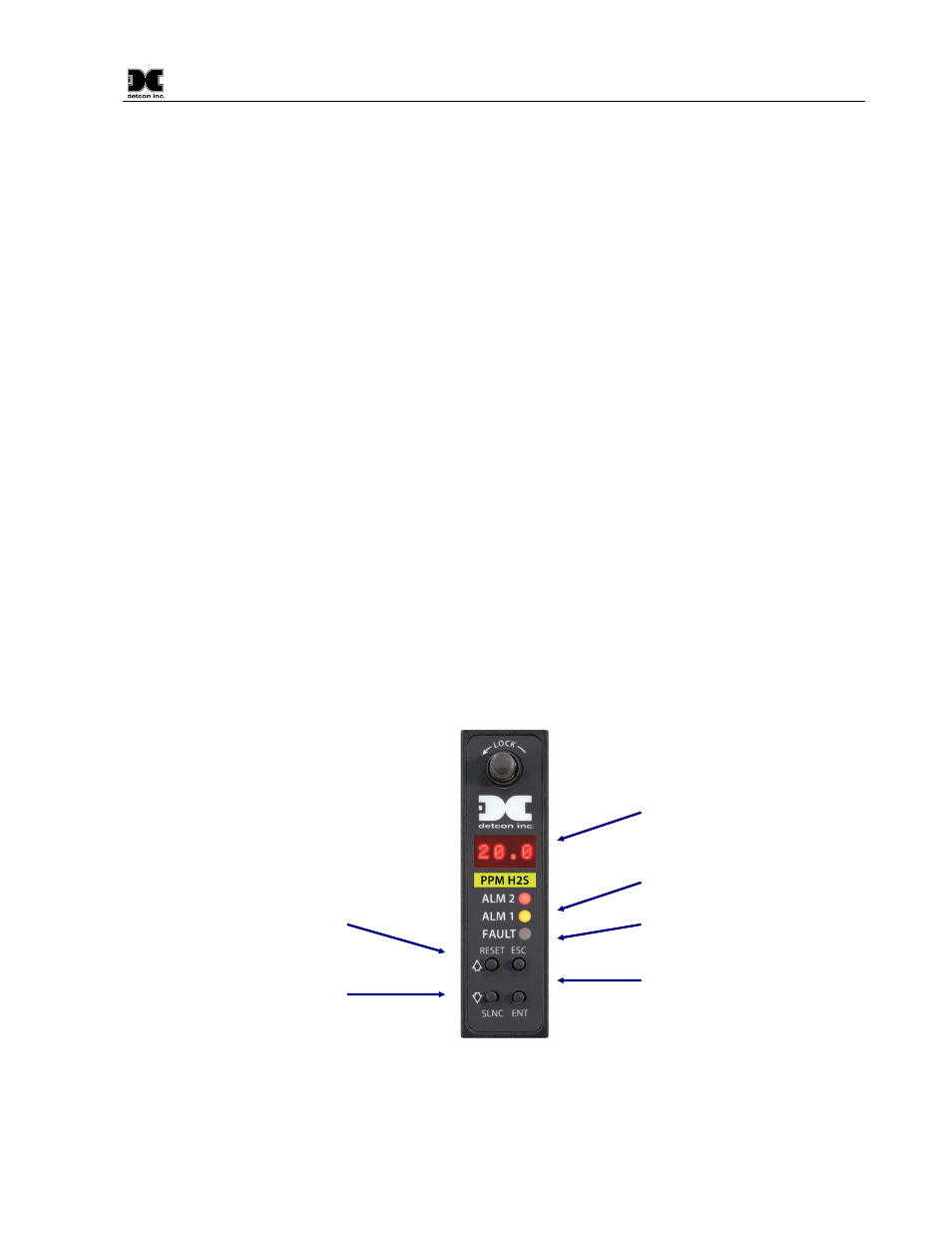
Four character display shows
numeric values and text. Scrolls text
for improved interactive function.
Alarm 1 and Alarm 2 LED
indicators.
RESET ALARM. The “UP”
pushbutton doubles as the Reset
Alarm function.
Fault Alarm LED indicator.
Four pushbuttons provided for
interactive user interface to configure
and view values and settings in
Controller. Keys are: ESCAPE,
ENTER,
×
UP and
Ø
DOWN.
SILENCE ALARM. The
“DOWN” pushbutton doubles
as the Silence Alarm function.
Figure 2 Front Panel (faceplate) of 10C Controller
10C Control Module Instruction Manual
Rev. 0.B
Page 1 of 25