Figure 1 system application diagrams – Detcon 10C Facilities User Manual
Page 5
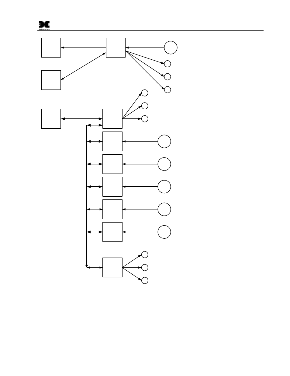
Model 10C
10C Control Module Instruction Manual Rev. 0.0
Page 1 of 14
10C
Controller
Master
Controller
4-20mA Current Input
4-20mA Current Output
Modbus
HOST
RS
48
5 M
OD
BU
S
CO
MM
10C
Controller
10C
Controller
10C
Controller
10C
Controller
10C
Controller
4-20mA Current Input
Facilities
Module
Fault
Alarm1
Alarm2
Sensor
O
U
T
P
U
T
D
E
V
IC
E
S
Sensor
Modbus
HOST
4-20mA Current Input
Sensor
4-20mA Current Input
Sensor
4-20mA Current Input
Sensor
4-20mA Current Input
Sensor
Z
O
N
E
1
O
U
T
P
U
T
S
Relay
Outputs
Z
O
N
E
2
O
U
T
P
U
T
S
Figure 1 System Application Diagrams
See also other documents in the category Detcon Equipment:
- 12B (16 pages)
- FL-10 (7 pages)
- 10C (29 pages)
- 10B (10 pages)
- 1212-N4X (9 pages)
- 812-N4X (9 pages)
- 1212B (5 pages)
- 612B (5 pages)
- 1610-N4X (28 pages)
- 1010-N4X (14 pages)
- 610-N4X (12 pages)
- 1610-N1 (4 pages)
- 810-N1-24VDC (10 pages)
- 410-N1-24VDC (4 pages)
- MCX-32-N1P (55 pages)
- RD-64X-N4X (41 pages)
- 880RA-N4X (36 pages)
- 880RA-N4X (23 pages)
- 880A-N1R (45 pages)
- 880A-N4X (50 pages)
- 880A-N4X (43 pages)
- X40-08-N4X (70 pages)
- 240 (33 pages)
- SW-AV1-N4 (12 pages)
- SW-AV2-DV1 (12 pages)
- A1V1 (9 pages)
- RXT-300 (47 pages)
- RXT-320 (31 pages)
- CXT-N4X (28 pages)
- SW-HMI-32-N4X (24 pages)
- SW-V1-DV2 (11 pages)
- SW-AV1-DV1 (14 pages)
- SW-AV2-DV2 (12 pages)
- SW-AV1-DV2 (12 pages)
- SmartWireless CX (33 pages)
- SmartWireless CXT (49 pages)
- CX-IR (38 pages)
- CX-DM (44 pages)
- CXT-IR (48 pages)
- CXT-DM (56 pages)
- P-1000 (28 pages)
- 1000 (32 pages)
- 1000_CO2 (32 pages)
- 1000_H2S (34 pages)