0 model 10 facilities module backplane pinouts – Detcon 10C Facilities User Manual
Page 17
Model 10C
10C Control Module Instruction Manual Rev. 0.0
Page 13 of 14
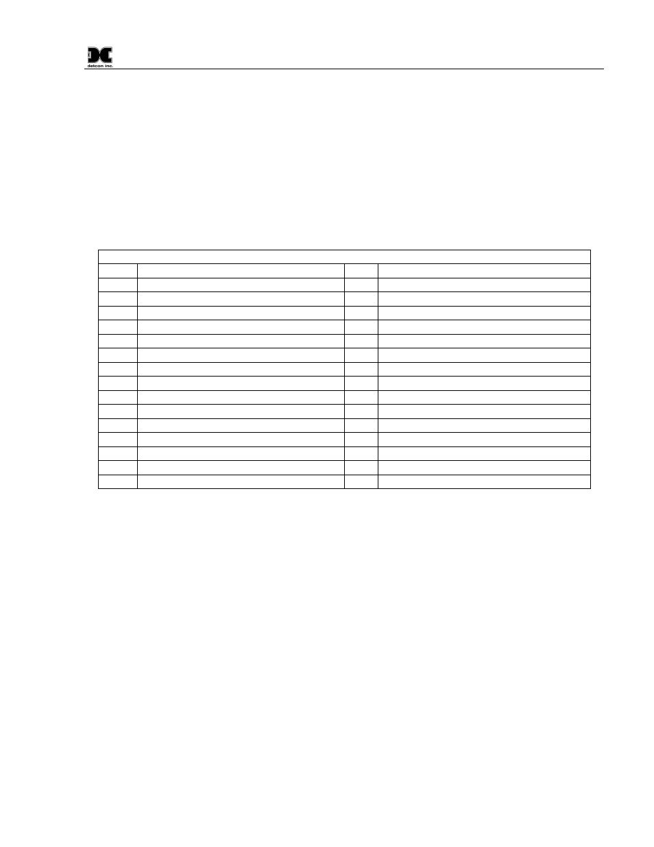
8.0 Model 10 Facilities Module Backplane Pinouts
Note that the RS485 Channel 1 is used by the FM to communicate to Modbus Slave devices: namely,
MOD 10 SSC modules. Note that RS485 Channel 2 is wired to pins C7 and C8, for RS485 signals A and
B, respectively. This second channel is the connection to the Master Host for the Facilities Module, on
which the FM is a Modbus Slave device.
The hardware difference between an FM and a 10C module is that the FM has removed the fuse
components that connect the Current Loop Input and Current Loop Output to the connector pin (note
components F1 and F4 are removed), and also the front panel for the FM has installed a mini-USB
connector.
MODEL 10C BACKPLANE PINOUT
A1
ALARM 1 N.O. CONTACT
C1
ALARM 2 CONTACT COMMON
A2
ALARM 1 N.C. CONTACT
C2
ALARM 2 CONTACT N.C.
A3
ALARM 1 CONTACT COMMON
C3
ALARM 2 CONTACT N.O.
A4
FAULT OPEN COLLECTOR
C4
FAULT CONTACT COMMON
A5
RS485-A, CHANNEL 1
C5
FAULT CONTACT N.C.
A6
RESET INPUT ACTIVE LOW
C6
FAULT CONTACT N.O.
A7
RS485 SHIELD
C7
RS485-A, CHANNEL 2
A8
RS485-B, CHANNEL 1
C8
RS485-B, CHANNEL 2
A9
ALARM 1 OPEN COLLECTOR
C9
(NOT CONNECTED)
A10
SENSOR POWER RETURN
C10
SENSOR POWER +
A11
SENSOR POWER RETURN
C11
SENSOR POWER +
A12
SENSOR POWER RETURN
C12
SENSOR POWER +
A13
ALARM 2 OPEN COLLECTOR
C13
(NOT CONNECTED)
A14
POWER IN RETURN
C14
POWER IN +
A15
POWER IN RETURN
C15
POWER IN +
A16
POWER IN RETURN
C16
POWER IN +