0 operator interface – Detcon 10C Facilities User Manual
Page 11
Model 10C
10C Control Module Instruction Manual Rev. 0.0
Page 7 of 14
the COS registers indicate a change, and then poll for all the 40000 data registers. Then write zero to the COS
registers.
A more complex RBE scheme is to only poll the registers, in response to COS bit indications, that have
changed since they probably change only one at a time. Then acknowledge by writing the COS image back to
the respective COS register; ie: a bit is set to 1 in the bit position where it is desired to reset an existing 1 bit.
This method reduces the Modbus traffic between the Host and an FM to be only a request for COS registers
and occasional read and acknowledge of changed data values. It is important that the Deadband value is set
reasonably. If set to 1, any change in concentration will register a COS bit =1. If set to 3, the concentration
will have to change by 3 counts to cause a COS bit = 1.
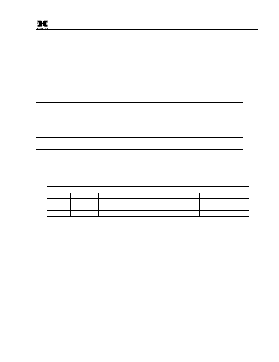
41001 3
Number Of Slaves
Read the number of Mod10 Slaves (0 – 32)
(set through Operator Interface)
41002
3/6
COS Word 1-16
Read Change of State on first 16 slaves. Acknowledge COS
on first 16 slaves.
41003 3/6
COS Word 17-32
Change of State on next 16 slaves. Acknowledge COS on
next 16 slaves
41004 3/6
Global Deadband
Concentration change from Last Reported Value for COS,
global for all 32 slaves.
41005 3
Local Alarm/Fault
Status
The FM produces a Logical-OR of the alarm/fault status of
each slave for the FM relays and annunciators except from
those in Test Mode.
2.0 Operator Interface
The Operator Interface to the FM consists of the Front Panel bracket indicators, display and pushbuttons.
The default state of the character display is called “Normal Operation” and consists only of indicating the
FM’s Modbus Address on the serial channel 2 Modbus line to a Modbus Master Host. While in the Normal
Operation Mode and by pressing the ESC pushbutton, a report of any bad communications with slaves will be
displayed. By pressing the ENT key momentarily a list of set parameters shall be presented on the display. The
display of the status of programmed parameters is called “Program Status”.
To go to Program Mode, whereupon configurations can be monitored or changed, the ENT key must be
pressed and held down for at least three seconds, and upon release, the Program Mode begins.
While in the Normal Operation mode, and while there are alarms to be reset or silenced, the pushbuttons
labeled “RESET” and “SLNC” may be used for such purpose.
REGISTER 41005 STATUS BITS
15
14
13
12
11
10
9
8
7
6
5
4
3
2
1
0
A2=Latchg Alarm2
A1=Latchg Alarm1
F=Latchg
Fault