Figure #5, Figure #6 – Detcon IR-542 User Manual
Page 12
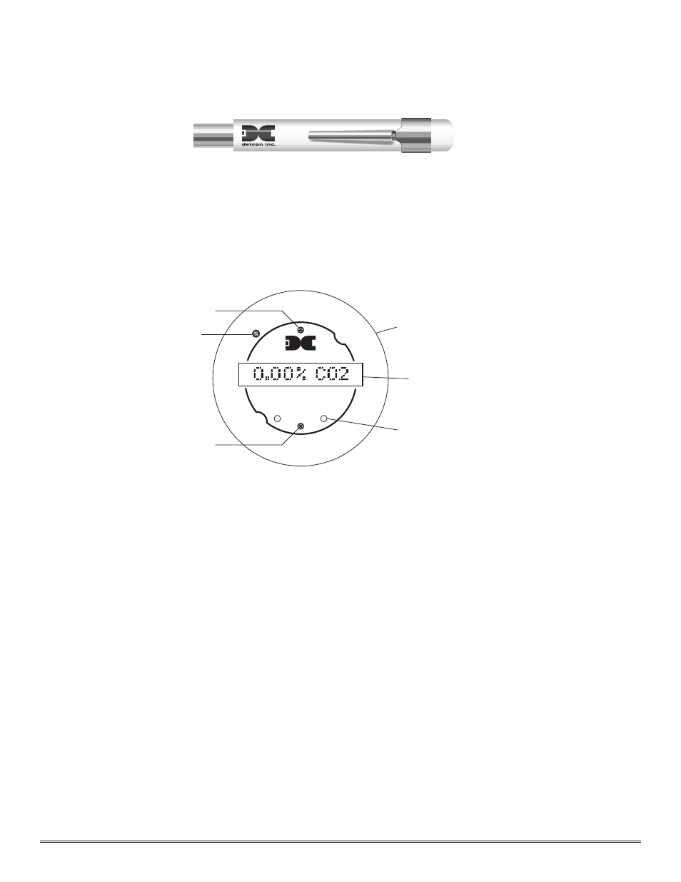
3.6.2 Programming Magnet Operating Instructions
Operator interface to MicroSafe™ gas detection products is via magnetic switches located behind the transmitter
face plate. DO NOT remove the glass lens cover to calibrate or change programming parameters. Two switches
labeled “PGM 1” and “PGM 2” allow for complete calibration and alarm level programming without removing the
enclosure cover, thereby eliminating the need for area de-classif ication or the use of hot permits.
A magnetic programming tool (see f igure 5) is used to operate the switches. Switch action is def ined as momentary
contact, 3 second hold, and 30 second hold. In momentary contact use, the programming magnet is waved over a
switch location. In 3 second hold, the programming magnet is held in place over a switch location for 3 or more
seconds. In 30 second hold, the programming magnet is held in place over a switch location for 30 or more sec-
onds. Three and thirty second hold is used to enter or exit calibration and program menus while momentary con-
tact is used to make adjustments. The location of “PGM 1” and “PGM 2” are shown in f igure 6.
NOTE: If, after entering the calibration or program menus, there is no interaction with the menu items for more
than 30 seconds, the sensor will return to its normal operating condition.
3.7 C
ALIBRATION
Material Requirements
*
Detcon PN 3270 MicroSafe™ Programming Magnet
*
Detcon PN 6132 Threaded Calibration Adapter
*
Span Gas containing the applicable calibration gas in air. Span gas concentration is recommended at 50% of
full-scale range (which is the factory default) at a controlled f low rate of 200 ml/min. Other concentrations can
be used as long as they fall within 10% to 90% of range. See section 3.7.2 for details.
3.7.1 Calibration Procedure - Zero
NOTE: Before performing a zero calibration, be sure there is no CO2 gas present.
a)
Enter the calibration menu by holding the programming magnet stationary over “PGM 1” (see figure 6) for 3 sec-
onds until the display reads
“1-ZERO 2-SPAN”, then withdraw the magnet. Note that the “CAL” LED is on.
b)
Next, enter the zero menu by holding the magnet stationary over “PGM 1” for 3 seconds until the display
reads:
“ZERO 0%”, then withdraw the magnet. The sensor has now entered the auto zero mode. When it is
complete the display will read
“ZERO COMPLETE” for 5 seconds and then return to the normal operations
menu,
“0.00 % CO2”.
Detcon Model IR-540/IR-542 Carbon Dioxide Sensor PG.12
Magnetic Programming Tool
Figure #5
detcon inc.
Program Switch #2
FLT
CAL
MicroSafe™ CO2 Gas Sensor
HOUSTON, TEXAS
PGM
2
PGM
1
MODEL
IR-540
CONTRAST
Fault & Cal LEDs
Program Switch #1
Menu Driven Display
Plug-in Microprocessor Control Circuit
Display Contrast Adjust
Figure #6