Figure #3, Figure #2 – Detcon IR-542 User Manual
Page 10
3.5.6 Remote Mounting Applications
Some sensor mounting applications require that the gas sensor head be remotely mounted away from the sensor
transmitter. This is usually true in instances where the gas sensor head must be mounted in a location that is diff i-
cult to access. Such a location creates problems for maintenance and calibration activities. Detcon provides the IR-
540/IR-541/IR-542 sensor in a remote-mount conf iguration in which the sensor (Model IR-540-RS, IR-541-RS or
IR542-RS) and the transmitter (Model IR-540-RT, IR-541-RT or IR542-RT) are provided in their own condulet hous-
ing and are interfaced together with a six conductor cable. Shielded cable is required and must be installed in its
own (unshared) conduit (use Alpha Wire Company #6342 cable). A maximum of 100 feet of separation is allowed.
Reference f igure 4 for wiring diagram.
Detcon Model IR-540/IR-542 Carbon Dioxide Sensor PG.10
BLU
YEL
BLK
WHT
mA
VDC Power In
4-20 mA Output
BRN
RED
Sensor
Base Connector Board
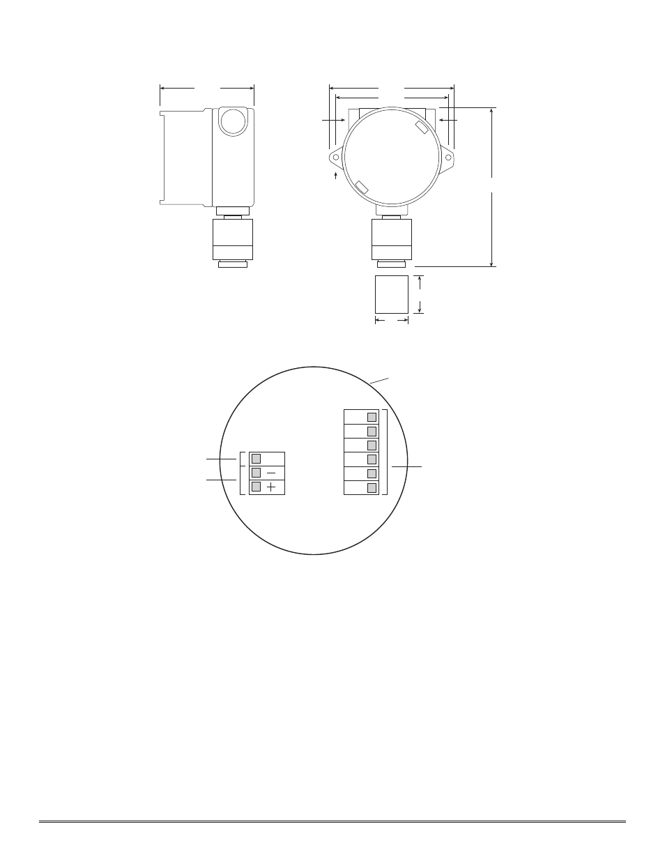
Figure #3
4 3/4"
3/4" NPT
1/4" Dia.
Mounting Holes
8 1/4"
6 1/8"
5 1/2"
3/4" NPT
Rainshield/
Splashguard
2"
2 1/8"
Figure #2