Figure #4 – Detcon IR-542 User Manual
Page 11
3.6 S
TART
U
P
Upon completion of all mechanical mounting and termination of all f ield wiring, apply system power and observe
the following normal conditions:
a)
The “Fault” LED is off.
b)
A reading of 0.00% CO2 should be indicated upon conclusion of a 12 second “warming up” cycle.
Note 1: If the display contrast needs adjustment, refer to section 3.10.
3.6.1 Initial Operational Tests
After a warm up period has been allowed for, the sensor should be checked to verify sensitivity to carbon dioxide
gas.
Material Requirements
*
Detcon PN 6132 Threaded Calibration Adapter
*
Span Gas 50% of full-scale range CO2 in air at a controlled f low rate of 200 ml/min.
a)
Attach the calibration adapter to the threaded sensor housing. Apply the test gas at a controlled f low rate of
200 ml/m. Observe that the LCD display increases to a level of 20% of full-scale range or higher.
b)
Remove the test gas and observe that the LCD display decreases to
“0.00 % CO2”.
Initial operational tests are complete. Detcon CO2 sensors are pre-calibrated prior to shipment and will, in most
cases, not require signif icant adjustment on start up. However, it is recommended that a complete calibration test
and adjustment be performed within 24 hours of installation. Refer to calibration instructions in later text.
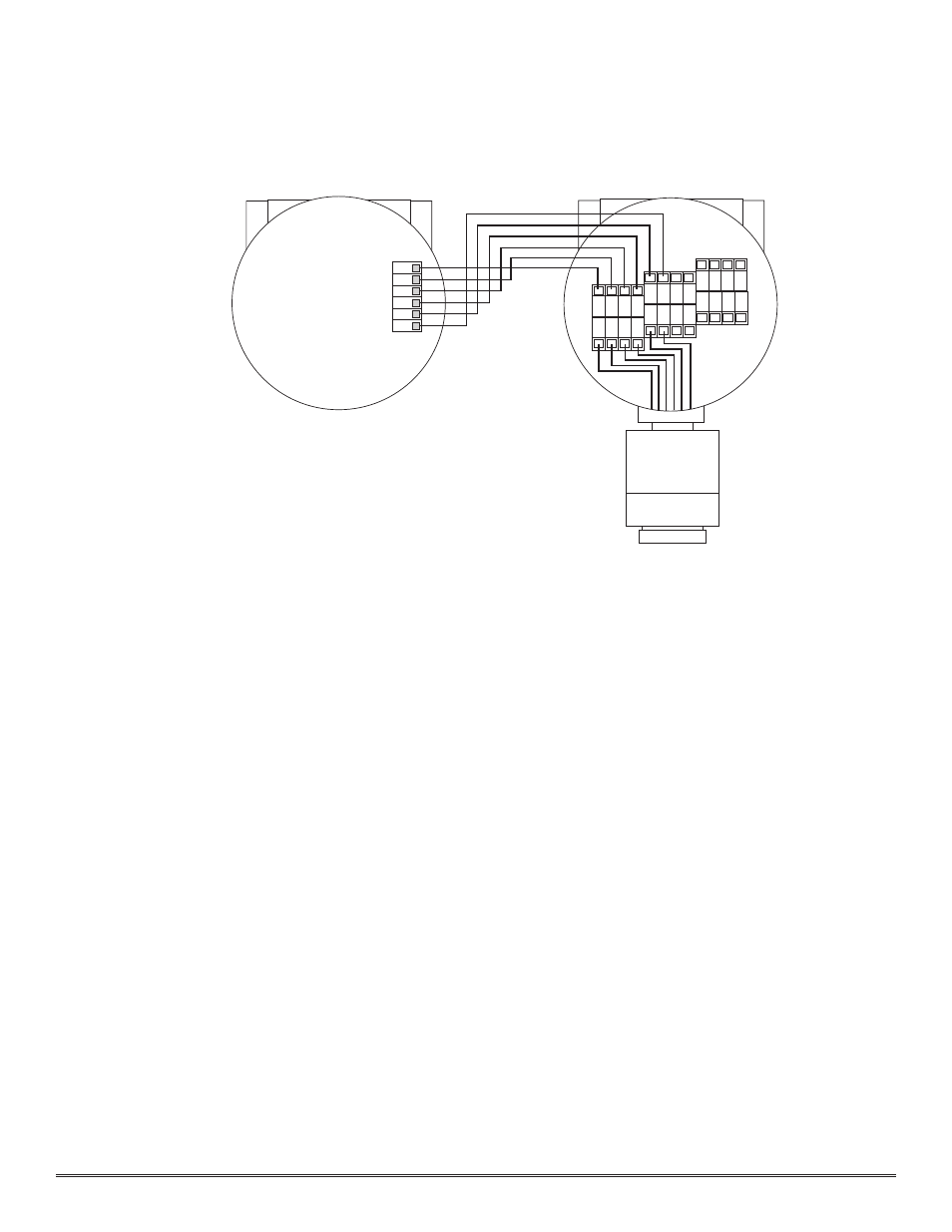
Detcon Model IR-540/IR-542 Carbon Dioxide Sensor PG.11
1 2 3 4
R
E
D
B
R
N
W
H
T
B
LK
Remote Transmitter
IR-540-RT
Remote Sensor
IR-540-RS
WHT
BLK
YEL
BLU
RED
BRN
5 6
Y
E
L
B
LU
Figure #4