Installation–continued – Ventamatic M SERIES DESIGNER FAN-LIGHTS User Manual
Page 2
NuVent
One Year Limited Warranty
Ventamatic, Ltd. warrants this product to be free from defects in
materials and workmanship for a period of one year from the
date of purchase. Warranty does not apply to product which
fails due to abuse, misuse, incorrect installation or improper
maintenance.
During the one-year warranty period, Ventamatic will repair or
replace, at its option, any product or part which has a factory
defect in workmanship or materials.
The foregoing shall constitute our sole and exclusive warranty
and our sole and exclusive liability, and is in lieu of any other
warranties, whether written, oral, implied or statutory. Under no
circumstances will Ventamatic be liable for special or
consequential damages occurring in connection with the use or
performance of the product or other indirect damages with
respect to loss of profits, revenue or property or cost of removal,
installation or reinstallation.
Some jurisdictions do not allow the exclusion or limitation of
incidental or consequential damages and some states do not
allow limitations on how long an implied warranty lasts, so the
above exclusions may not apply to you.
This warranty gives you specific legal rights and you may have
other rights which vary from state to state and province to
province.
Fill in information below for your records:
_________________________________________________________
Date of Installation Model # and Product Description
For warranty service or information, please visit the Ventamatic web site at
www.bvc.com or call 1-800-433-1626.
FIGURE 5
INSTALLATION–continued
DESIGNER LIGHT ATTACHMENT
10. Attach the mounting bracket (Fig 6A) to the motor
plate (Fig 6 B) with four 1/2" pan head screws (provided).
11. Insert the motor plate in the housing and secure
motor plate with motor plate screw removed in Step 4.
14. Insert the quick connector on the Designer Light frame.
15. Position the keyhole slots in the Designer Light frame
over the two screws in the mounting bracket. Twist in place
and secure Designer Light frame by tightening screws in
mounting bracket.
16. Insert two 60W incandescent bulbs or two compact
fluorescent bulbs into light sockets.
17. Install glass dome. Twist slightly to secure.
12. Insert the motor quick connector.
13. Insert the two 2" Phillips pan head screws (provided) in
the mounting bracket. See Figure 7.
FIGURE 7
FIGURE 6
6A
6B
6B {
{
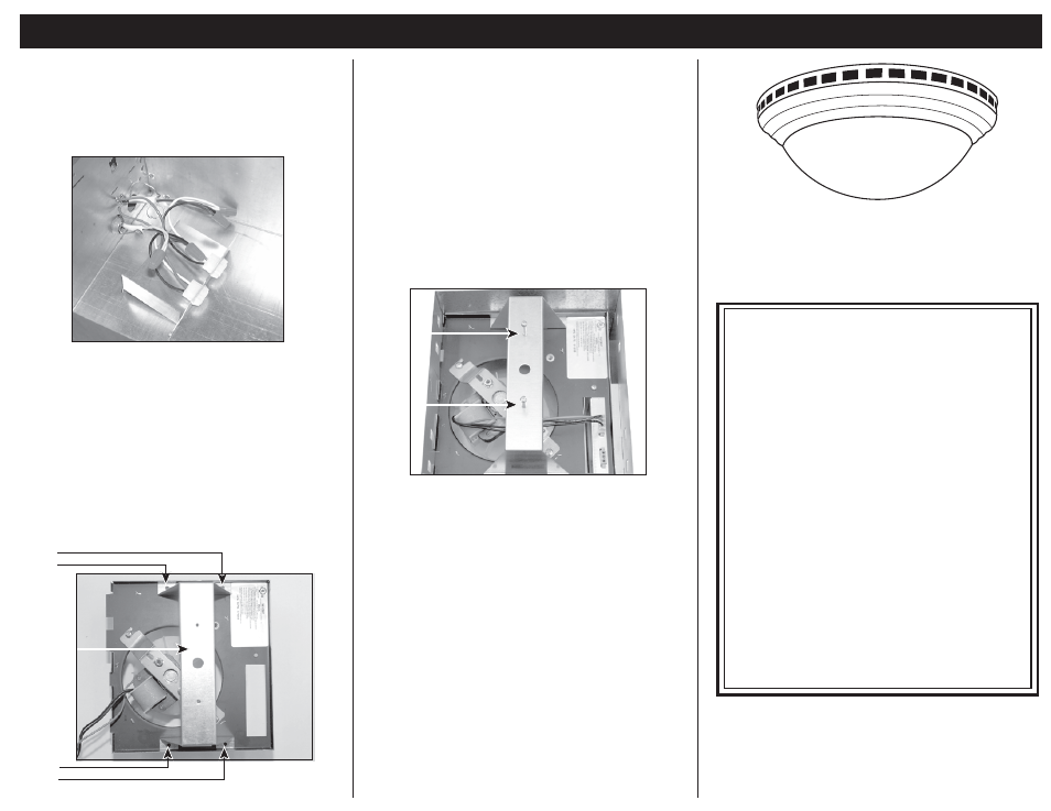
7. Connect the supply wiring to the fan wiring using
approved wire nuts: black to black and white to white.
Connect ground wire to green grounding screw on side of
housing. Repeat wiring to second plug for light.(Fig.5).
8. Replace the electrical box removed in Step 4.
DUCT ATTACHMENT
9. Secure 4" diameter round duct to the fan's duct collar.
Ducting should terminate per local/municipal building code.
Models:
NXMD_ _1AB
( _ _ = CFM rating)
NXMD_ _1OB
( _ _ = CFM rating)
NXMD_ _1WH
( _ _ = CFM rating)