Ventamatic M SERIES DESIGNER FAN-LIGHTS User Manual
M series designer fan-lights, Planning instalación, Installation
M SERIES DESIGNER FAN-LIGHTS
SAFETY INSTRUCTIONS
WARNING: TO REDUCE THE RISK OF FIRE, ELECTRIC SHOCK,
OR INJURY TO PERSONS, OBSERVE THE FOLLOWING:
1. Use this unit only in the manner intended by the
manufacturer. If you have questions, contact the manufacturer.
2. Before servicing or cleaning unit, switch power off at service panel
and lock the service disconnecting means to prevent power from
being switched on accidentally. When the service disconnecting
means cannot be locked, securely fasten a prominent warning device,
such as a tag, to the service panel.
3. Installation work and electrical wiring must be done by qualified
person(s) in accordance with all applicable codes and standards,
including fire-rated construction.
4. Sufficient air is needed for proper combustion and exhausting of
gases through the flue (chimney) of fuel burning equipment to prevent
back drafting. Follow the heating equipment manufacturer's
guideline and safety standards such as those published by the
National Fire Protection Association (NFPA) and the American Society
of Heating, Refrigeration and Air Conditioning Engineers (ASHRAE)
or local code authorities.
5. When cutting or drilling into wall or ceiling, do not damage electrical
wiring and other hidden utilities.
6. Ducted fans must always be vented to the outdoors.
7. If this unit is to be installed over a tub or shower, it must be marked
as appropriate for the application and be connected to a GFCI
(Ground Fault Circuit Interrupter) – protected branch circuit.
8. NEVER place a switch where it can be reached from a tub or shower.
CAUTION: FOR GENERAL VENTILATING USE ONLY!
Do Not Use To Exhaust Hazardous Or Explosive Materials Or Vapors.
• Screwdriver
• Hammer
• Electric drill
• Wire nuts
• Safety glasses
• Ruler or
straight edge
• Keyhole saw or
jig saw
• Wire cutters
• Wire stripper
TOOLS FOR INSTALLATION:
The Nuvent Designer Fan-Lights listed in these instructions are designed
for use in the bathroom. Approved for installation above a tub or
shower enclosure when connected to a UL Listed GFCI protected branch
circuit. Not for use in kitchen.
NEW CONSTRUCTION: When installing this product in new
construction the housing should be mounted with wiring and duct
during the rough-in phase. The blower unit and dome light should be
installed after the ceiling is finished.
EXISTING CONSTRUCTION: Installation for existing construction
requires access above or behind planned installation location.
WIRING: This product requires 120v AC standard house wiring (with
ground) from the power source through a standard wall switch
(switches) to the unit's housing. NuVent switch model R2SW can be
ordered separately for use with this unit.
DUCTING: For best performance use the following guidelines when
planning for the installation of duct work for this unit:
1. Use correct duct size as indicated in installation instructions. (Step 8)
2. Ducting should run from the fan to the outside of the home or
building. The duct run should be as short and as straight as
possible.
3. Identify the ducting requirements per local/municipal code.
4. When using flexible duct, avoid kinks and always expand the
ducting as fully as possible.
PLANNING
INSTALACIÓN
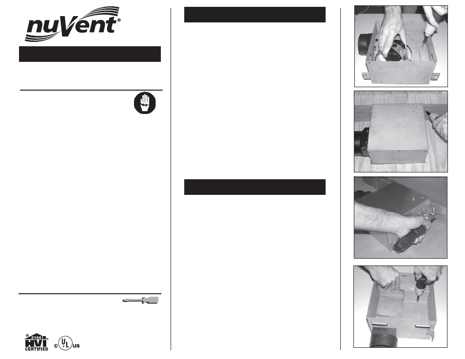
1. Remove blower assembly before installing housing. Remove screw
from blower assembly then slide assembly sideways and lift out. (Fig. 1)
INSTALLATION IN NEW CONSTRUCTION
2. Attach housing to joist through keyhole mounting tabs (Fig. 2) or
adjustable hanger bars (Fig. 3) using nails or screws. (Do not
tighten.) Adjust the housing so it will not extend past the finished
ceiling. The outer edge of the housing should be recessed 1/8" to
1/4" from the finished ceiling.
3. Once housing is correctly positioned, it is important to tighten
screws or add additional nails to hold fan housing firmly in
position. This prevents vibration and noise.
WIRING
Turn off electrical power at service panel.
4. Remove screw that holds electrical box cover. (Fig. 4)
5. Run 120v AC wiring with ground from the wall switch (switches) to
the fan electrical box.
6. Remove one (two) of the electrical knockouts from the fan and pull
supply wiring into the electrical box.
INSTALLATION
FIGURE 4
FIGURE 3
FIGURE 2
FIGURE 1