Figure 2-b dimensions, 5 installing desiccant – Van Air Systems PLD 8-14.5 / 36-14.5 User Manual
Page 4
PAGE 4
J
Hammer
Union
4"
4"
4"
6"
6"
6"
6"
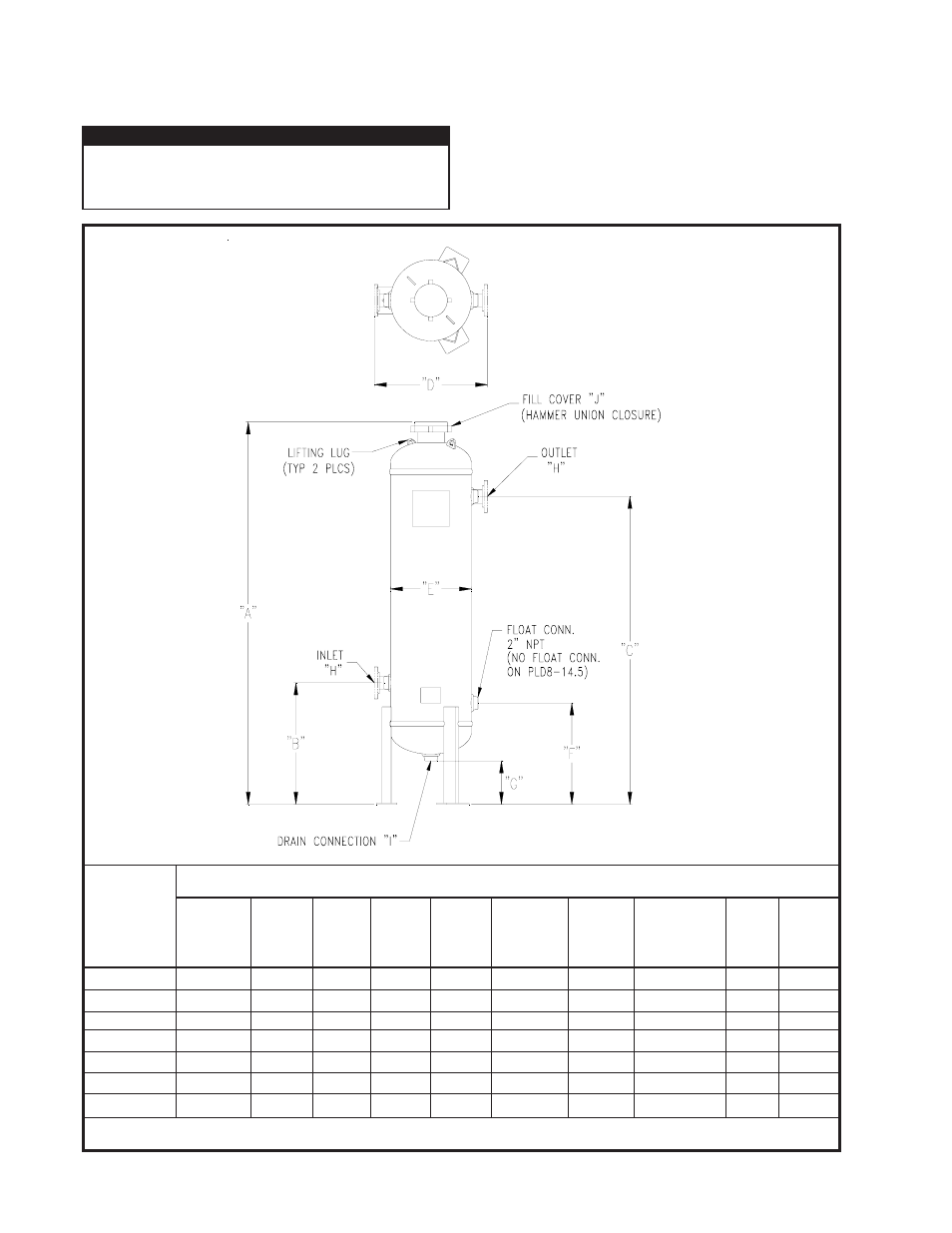
FIGURE 2-B DIMENSIONS
Open fill cover and add the proper amount of
pre-bed material and desiccant to fill the dehydrator to the
MAXIMUM LEVEL; then level off the top off the bed.
(Reference SECTION 4.3 for desiccant installation instruc-
tions) USE VAN GAS ABSORBENT DESICCANT ONLY!
Close fill hatch. Make sure that the inlet and outlet shut-off
valves, and manual drain valve are closed.
2.5 INSTALLING DESICCANT
MODEL
PLD8-14.5
PLD12-14.5
PLD16-14.5
PLD20-14.5
PLD24-14.5
PLD30-14.5
PLD36-14.5
DRYER DIMENSIONS
(INCHES)
H
Inlet/Outlet
2" NPT (f)
2" NPT (f)
2" NPT (f)
2" NPT (f)
3" RF FLG **
3" RF FLG **
3" RF FLG **
C
Outlet
Height
74"
76"
76"
76"
71-5/8"
75-1/2"
76-3/16"
D
In to Out
Width
11-7/8"
16"
19-1/4"
23-1/4"
36"
42"
51"
E
Outside
Dia.
8-5/8"
12-3/4"
16"
20"
24"
30"
39"
F
Float
Height
N/A
25"
25"
25"
21-1/8"
25"
25-11/16"
G
Drain
Height
14-1/2"
12-3/4"
11-3/4"
10-3/4"
5-13/16"
8-1/16"
6-1/2"
A
Overall
Height
88-15/16"
94-3/8"
95-11/16"
94-3/8"
92-11/16"
99-5/16"
101-15/16"
B
Inlet
Height
33"
30"
30"
30"
26-1/8"
30"
30-11/16"
I
Drain
(NPT)
1"
2"
2"
2"
2"
2"
2"
DEPRESSURIZE DEHYDRATOR COM-
PLETELY BEFORE ATTEMPTING TO RE-
MOVE FILL COVER.
IMPORTANT
** All flanges are 600#