0 purpose, 0 installation, 1 location – Van Air Systems PLD 8-14.5 / 36-14.5 User Manual
Page 2: Maximum capacities - mscfd
PAGE 2
1.0 PURPOSE
MODEL
PLD8-14.5
PLD12-14.5
PLD16-14.5
PLD20-14.5
PLD24-14.5
PLD30-14.5
PLD36-14.5
2.0
INSTALLATION
2.1 LOCATION
CAPACITY: The chart below indicates the maximum flow
rate through the dehydrator for a 24 HOUR period. To
calculate the capacity for a rate per minute just multiply the
MSCFD RATE (from chart ) by 0.6944 example:
A PLD12-14.5 operating at 100 PSIG has a maximum
MSCFD rate of 119. To figure the SCFM multiply 119
MSCFD x 0.6944 which equals 83 SCFM
NOTE: This is the MAXIMUM instantaneous flow that can
be processed through the dehydrator without deteriora-
tion of the drying performance.
OPERATING PRESSURE: More gas can be processed
through the dehydrator at higher pressures. Locate the
dehydrator at the highest practical pressure, but do not
exceed the maximum rated working pressure of the dehy-
drator. Refer to the capacity chart located below.
AFTERCOOLING: If the gas being processed has been
compressed mechanically, an aftercooler, finned tubing or
extended run of piping will usually be necessary to reduce
the inlet gas temperature to the dehydrator.
MAXIMUM CAPACITIES - MSCFD
1,000 STANDARD CUBIC FEET PER DAY
1300
PSIG
735
1363
2158
3558
5128
7968
13655
1200
PSIG
679
1259
1994
3287
4738
7362
12616
1100
PSIG
623
1156
1830
3017
4348
6756
11578
1000
PSIG
567
1052
1666
2746
3958
6150
10539
750
PSIG
428
793
1255
2069
2983
4635
7943
100
PSIG
64
119
188
310
447
695
1191
MAXIMUM
WORKING
PRESSURE
1450 PSIG
1450 PSIG
1450 PSIG
1450 PSIG
1450 PSIG
1450 PSIG
1450 PSIG
PART
NO.
80-1477
80-1442
80-1483
80-1482
80-1484
80-1485
80-1486
ALWAYS PROCESS THE GAS THROUGH THE
DEHYDRATOR AT THE LOWEST TEMPERA-
TURE AND THE HIGHEST PRESSURE
.
IMPORTANT
CAUTION
The gas temperature should not exceed:
100°F for GASDRY PRIME
80°F for GASDRY PEAK
100°F for GASDRY MAX
1400
PSIG
791
1467
2322
3829
5518
8574
14694
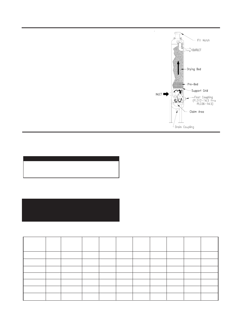
A Pipeline Dehydrator removes the water vapor (humidity) present in the
gas stream. The process cleans and dries the gas as it flows through the
vessel which is filled with a special drying agent (desiccant). The
dehydrator operates automatically. There are no moving parts and no
external source of power is required.
"Wet" natural gas enters the lower portion of the dryer where liquid water
and solid particles are separated by gravity and fall to the bottom of the
vessel. The gas moves upward through the prebed and drying bed of
Van Gas desiccant tablets. The tablets attract and absorb moisture from
the gas as it flows through the desiccant bed. The tablets dissolve
gradually as they absorb the moisture and the liquid falls to the bottom of
the vessel. The liquid run off in the prebed creates an extended surface
area capable of removing additional moisture from the gas. This con-
serves the absorbent desiccant tablets. The "dry" natural gas flows
through the dryer outlet.
The solution of dissolved desiccant and water that falls into the claim
area at the bottom of the vessel must be drained regularly to prevent the
vessel from flooding. An automatic drain valve can be installed to
prevent the vessel from flooding.
The ability of a dehydrator to dry natural gas is dependent
on the correct location of the unit. Temperature and pres-
sure are the keys to selecting the proper location.
INLET TEMPERATURE: Lower inlet gas temperatures will
result in lower moisture content at the dehydrator outlet.
Locate the dehydrator at the point where temperature is the
lowest.
1450
PSIG
819
1519
2404
3964
5714
8877
15213