Van Air Systems PLD 8-14.5 / 36-14.5 User Manual
Page 3
PAGE 3
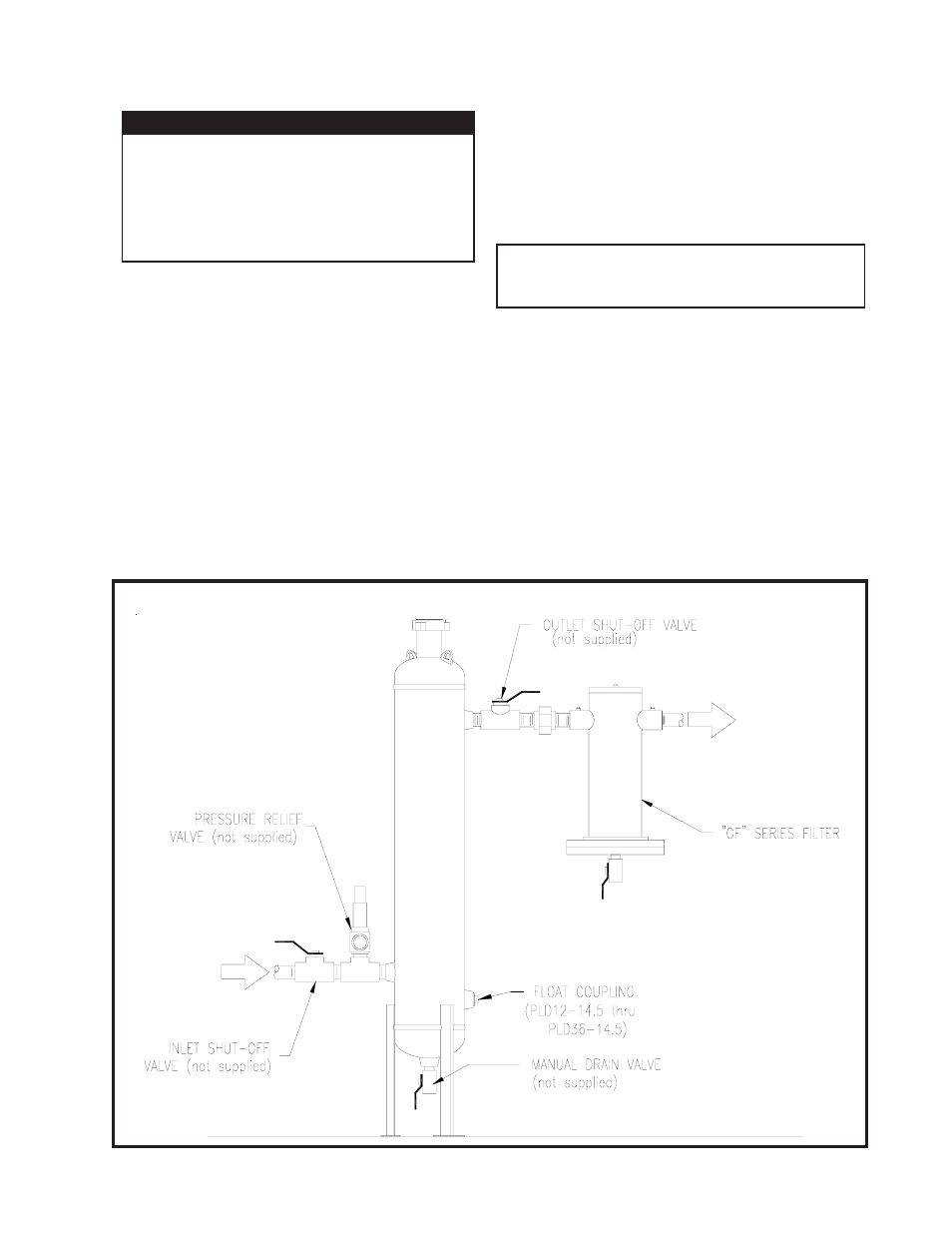
FIGURE 2-A RECOMMENDED INSTALLATION
2.3 INLET AND OUTLET PIPING
NOTE
Inlet and outlet shut-off valves will make start-up
and addition of desiccant easier.
Two shut-off valves should be installed (not furnished
with dehydrator)--one at dehydrator inlet and another at
dehydrator outlet. See Figure 2-A Recommended
Installation.
Connect the inlet piping and outlet piping as shown in
Figure 2-A.
2.4 DRAIN VALVE
Install a drain valve (not furnished with dehydrator) in the
drain coupling at the bottom of the tower (except on
PLD8-14.5). A float/auto drain valve system is available.
Contact Van Gas for details.
IMPORTANT
COMPLY WITH ALL FEDERAL, STATE, AND
LOCAL REGULATIONS CONCERNING IN-
STALLATION OF NATURAL GAS SYSTEMS.
COMPLIANCE WITH AND KNOWLEDGE OF
ALL REGULATIONS IS THE RESPONSIBIL-
ITY OF THE INSTALLER.
Install a pressure relief valve in the up-stream
piping (relief valve not furnished). A relief valve
must be installed to conform with the ASME
Boiler and Presssure Vessel Codes, Section VII,
Division 1 UG-125, Paragraph (1) and OSHA
standards. Also comply with all applicable
Federal, State and Local codes.
2.2 PIPING & ANCILLARY EQUIPMENT
Make sure that the gas temperature is not over the maxi-
mum for the desiccant being used. If gas temperature is too
high, cool it prior to the dehydrator.
Mount the dehydrator on a level surface capable of sup-
porting the weight of the vessel, such as a cement pad or
a skid.
2.5 AFTERFILTER
Van Gas "GF" Series Filters can be installed downstream
of the dehydrator to remove particulate contamination
from the natural gas. Contact Van Gas for details.