Van Air Systems HL-2500 User Manual
Page 14
PAGE 14
USING THE CYCLE SAVER CONTROL
SECTION 8
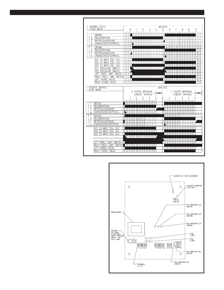
FIGURE 8B TIMING CHART FOR CYCLE SAVER
8.3 FAILURE TO SWITCH ALARM
The FAILURE TO SWITCH ALARM is operational in
the FIXED and AUTO modes.
The dryer is continuously being monitored for
switching failure. Two pressure switches monitor the
pressure in the desiccant towers. If pressure is
present in the tower that should be in the regenerat-
ing stage, the alarm is activated. The printed circuit
board gives the dryer 90 seconds to depressurize
after tower changeover before the alarm is activated.
If one or both of the pressure switches fail, the
alarm is NOT activated, but the dryer is switched into
a 10 minute fixed cycle.
When the alarm is activated, the FAILURE TO
SWITCH LED is illuminated. The alarm does not
stop the dryer from cycling. The FAILURE TO
SWITCH ALARM is a latching alarm. Once the
problem causing the switching failure is corrected,
the FAILURE TO SWITCH RESET PUSHBUTTON
must be pressed to reset the alarm. If the alarm is
reset and the problem is not corrected, the alarm will
be re-activated after 90 seconds.
The switching failure alarm will activate when:
• The inlet transfer valve does not change
positions and does not direct the process flow
through the proper tower.
• The purge exhaust valve does not open on the
regenerating tower or if tower pressure in the
regenerating tower does not drop below 40 psig.
• The purge exhaust valve does not close on the
regenerating tower to allow repressurization.
The GENERAL ALARM contact is closed when this
alarm is activated.
8.4 GENERAL ALARM
The general alarm contact was provided for the customer to wire the
dryer’s alarm into a main control room, or to a warning light or horn.
The contact is a normally open dry contact. The contact is closed if
the SWITCHING FAILURE ALARM has been activated. The contact
will only reset if the alarm condition is corrected.
FIGURE 8C CYCLE SAVER PRINTED CIRCUIT BOARD
8.5 PRINTED CIRCUIT BOARD (LEDs)
The Humidity Indication LED (RED) is on when the humidity is above
the set point.
The SV1 Indication LED (GREEN) is on when the valve is energized.
The SV2 Indication LED (GREEN) is on when the valve is energized.
The SV3 Indication LED (GREEN) is on when the valve is energized
The PS1 Indication LED (GREEN) is on when the switch is closed.
The PS2 Indication LED (GREEN) is on when the switch is closed.
Note: These LEDs are located on the inside of the control box on
the printed circuit board. Figure 8C illustrates the LEDs loca-
tions.
LEFT TOWER PRESSURE (PS1)
RIGHT TOWER PRESSURE (PS2)