Start-up – Van Air Systems HL-200 - HL2000 User Manual
Page 11
PAGE 11
START UP
SECTION 5
5.1 START UP
WARNING
BEFORE STARTING THIS DRYER, FOLLOW THE INSTALLATION
INSTRUCTIONS AND PROCEDURES COMPLETELY. SERIOUS
PERSONAL INJURY CAN RESULT IF INSTRUCTIONS ARE NOT
CAREFULLY AND COMPLETELY FOLLOWED.
DO NOT REMOVE, REPAIR, OR REPLACE ANY ITEM ON THIS
DRYER WHILE IT IS PRESSURIZED.
For the Standard Control Box, make sure the Stop button is pressed.
For the Cycle Saver and Emcon II Control Boxes, make sure that the
Power switch is in the OFF position.
If the dryer is being started up for the first time or after the
desiccant has been changed, the purge mufflers must be removed.
The dryer should be operated until no desiccant dust is visible at
the purge valves. Then the mufflers can be reinstalled. See
Section 2.2 for safety precautions concerning the desiccant dust.
WARNING
WHEN OPERATING THIS DRYER WITHOUT THE MUFFLERS
INSTALLED, USE HEARING PROTECTION.
If bypass piping was installed on this dryer as outlined in SECTION 4.2,
close the inlet and outlet isolation valves. Open the bypass valve.
Pressurize the air system. Once the air system is pressurized, slowly
open the inlet isolation valve. DO NOT open the outlet isolation valve.
To start the dryer with a Standard Control Box, press the Run button
which will light the Run LED. For Cycle Saver and Emcon II Control
Boxes, place the Power switch in the ON position. One tower will
already be pressurized. The other tower will depressurize. The purge
valve on the tower that is not pressurized will be open, air should be
exhausting from the muffler.
Dryers equipped with CYCLE SAVER or EMCON II controls will begin a
20 minute start up cycle. While in the start up cycle the dryer will
operate for 5 minutes on each tower to allow the humistat(s) to reach
equilibrium. Any time the dryer is restarted after a loss of power or
pressure in both towers, it will restart in the start up cycle.
The dryer is equipped with a purge metering valve. The setting should
be checked before placing the dryer on stream.
5.2 ADJUSTING THE PURGE FLOW
IMPORTANT
NEVER OPERATE THE DRYER WITH THE PURGE METERING
VALVE CLOSED. IF THE VALVE IS CLOSED, THE TOWERS WILL
NOT REPRESSURIZE AND SWITCHING FAILURE WILL OCCUR.
DO NOT ADJUST THE PURGE METERING VALVE ABOVE OR
BELOW THE RECOMMENDED SETTING FOR THE OPERATING
CONDITIONS OF THIS INSTALLATION. IMPROPER SETTING MAY
CAUSE POOR DRYER PERFORMANCE AND/OR EXCESSIVE USE
OF PROCESS AIR.
The purge flow can be adjusted for the operating conditions. Standard
dryers are equipped with a micrometer type needle valve. The valve can
be adjusted to the desired setting.
This dryer was shipped with the purge flow set for the rated inlet flow at
100 PSIG. Reference Section 3.1 for rated flow. This setting should be
correct for most installations. Before placing the dryer on stream, check
the purge metering valve setting.
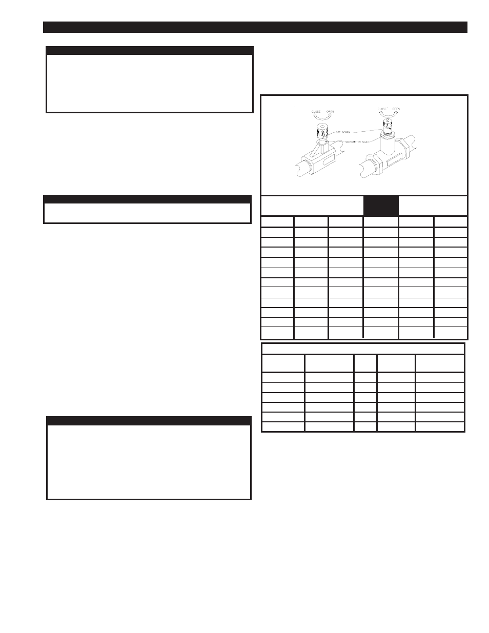
Figure 5B shows the purge flow required for each model. This flow is
required to properly regenerate the desiccant beds.
If the dryer is being operated at a pressure other than inlet rated
MODEL
HL-200
HL-250
HL-375
HL-500
HL-650
HL-800
HL-1000
HL-1250
HL-1500
HL-1750
HL-2000
60 PSIG
3.5 turns
3.6 turns
4.5 turns
5.6 turns
2.7 turns
2.8 turns
3.0 turns
3.4 turns
3.8 turns
4.0 turns
4.2 turns
80 PSIG
3.3 turns
3.4 turns
4.0 turns
4.6 turns
2.6 turns
2.7 turns
2.8 turns
3.0 turns
3.3 turns
3.5 turns
3.9 turns
FACTORY
SETTING
100 PSIG
3.2 turns
3.3 turns
3.8 turns
4.2 turns
2.5 turns
2.6 turns
2.7 turns
2.9 turns
3.0 turns
3.2 turns
3.4 turns
120 PSIG
3.1 turns
3.2 turns
3.7 turns
4.0 turns
2.3 turns
2.5 turns
2.6 turns
2.7 turns
2.9 turns
3.0 turns
3.2 turns
150 PSIG
3.0 turns
3.1 turns
3.5 turns
3.8 turns
2.2 turns
2.3 turns
2.5 turns
2.6 turns
2.7 turns
2.8 turns
3.0 turns
FIGURE 5A PURGE METERING VALVE SETTINGS
1/2" & 3/4" VALVES used on
models HL-200 THROUGH HL-500
1" VALVE used on
models HL-650 through HL-2000
FIGURE 5B REQUIRED PURGE FLOW
DRYER
MODEL
HL-200
HL-250
HL-375
HL-500
HL-650
HL-800
5.3 CONDITIONING THE DESICCANT BED
To condition the desiccant bed, the dryer is operated without any outlet flow,
while the towers regenerate with purge air.
To start the dryer with a Standard Control Box, press the Run button which
will light the Run LED. For Cycle Saver and Emcon II Control Boxes, place
the Power switch in the ON position.
Dryers equipped with the Standard Contol Box should be set on the 10 minute
time cycle. Dryers equipped with Emcon II and Cycle Saver should be set in
the Fixed Mode. Observe the dryer for several cycles. Make sure that it is
operating properly.
At initial start up or after extended shutdowns (over one month), the dryer may
take 24 to 48 hours of continuous operation for the bed to be conditioned.
Moisture that has accumulated on the desiccant bed should be removed
before the dryer is placed on stream.
Once the moisture indicator on the dryer turns blue, the desiccant bed is
ready. Place the dryer on stream by opening the outlet isolation valve. Make
sure that the by-pass valve is closed.
PURGE
FLOW
36.0 SCFM
45.0 SCFM
67.5 SCFM
90.0 SCFM
117.0 SCFM
144.0 SCFM
DRYER
MODEL
HL-1000
HL-1250
HL-1500
HL-1750
HL-2000
PURGE
FLOW
180.0 SCFM
225.0 SCFM
270.0 SCFM
315.0 SCFM
360.0 SCFM
conditions, the purge metering valve must be adjusted to maintain the
required purge flow rate listed in Figure 5B.
Determine the dryer minimum operating pressure. Using the chart in Figure
5A, find the valve setting for that pressure. The valve is equipped with a set
screw which must be loosened before the valve is adjusted. Adjust the needle
valve to the desired setting. Tighten the set screw to prevent tampering.