F. balance bar adjustment and operation, Diagram 9 diagram 10, Diagram 8 diagram 7 – Tilton Firewall – Aluminum & Steel (98-1203) User Manual
Page 4: Force distribution
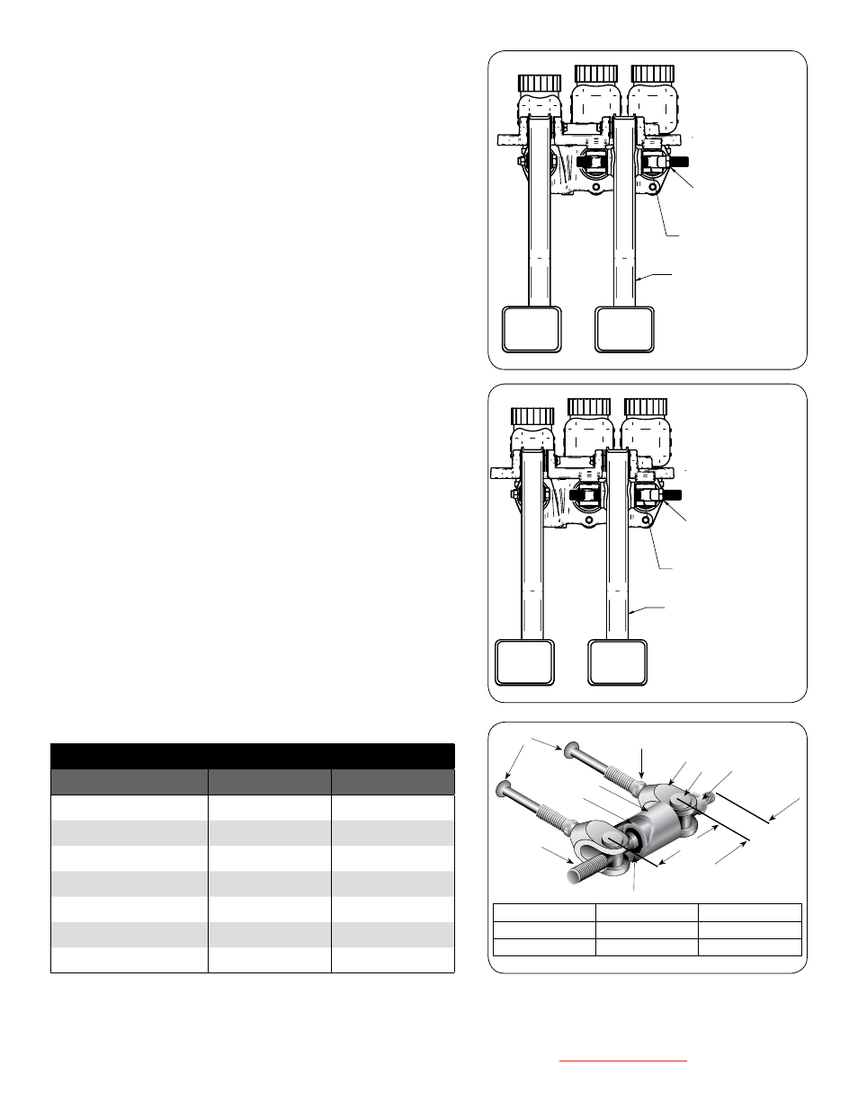
F. Balance Bar aDjustMent anD operation
When running on pavement, you want the front tires to lock-up with slightly less
pedal pressure than the rear tires. This will help to keep the car stable and prevent it
from going into a spin.
1. Loosen the jam-nut on the adjusting shaft (Item 3 in Diagram 10).
A jam-nut is not used with a remote adjuster.
2. Turn the adjusting shaft (Item 8 in Diagram 10) by hand or with the remote cable
adjuster so that it advances the spherical bearing closer to the selected master
cylinder, increasing the braking force produced by that master cylinder (Chart 2).
The balance bar must be adjusted with the pedal in the relaxed position (Diagram
D). It will not rotate while depressing the pedal.
3. The balance bar has a fairly large adjustment range. However, if you find that
what you need is outside of the adjustment range, you will need to make a master
cylinder bore size change. There are three possible changes that can be made
(See below). All three will allow the spherical joint to move back towards the
center position.
a) Decrease the bore size of the master cylinder closest to the spherical joint
by 1/8". This will decrease the amount of pedal force required from the foot
and increase the amount of pedal travel.
b) Increase the bore size of the master cylinder farthest from the spherical
joint by 1/8". This will increase the amount of pedal force required by the
foot and decrease the amount of pedal travel.
c) Increase the bore size of the master cylinder farthest from the spherical
joint by 1/16". Decrease the other master cylinder bore size by 1/16".
This will maintain the amount of force and pedal travel while making a
relatively large change to the front/rear brake bias.
4. Whenever making an adjustment, remember to tighten the jam-nut (Item 3 in
Diagram 10) afterwards. A jam-nut is not required when a Remote Brake Bias
Adjuster is used.
Center
7
Adjustment
9
1
2
3
5
6
8
4
1. Clevis
4. Retaining Ring Clips 7. Pushrod
2. Barrel Nuts
5. Pivot Sleeve
8. Adjusting Shaft
3. Jam-nuts
6. Spherical Bearing
9. Jam-nuts (Pushrod)
Diagram 9
Diagram 10
STIFF, LIGHTWEIGHT
TUBULAR STEEL
CLUTCH AND BRAKE
PEDALS
JAM NUT SECURES BIAS BAR SETTING.
FOR REMOTE CABLE ADJUSTER, REMOVE
JAM NUT AND SECURE CABLE TO END OF
BIAS BAR WITH CABLE COUPLER
CLEVIS DESIGNED FOR
MINIMUM FREE PLAY WITH
OR WITHOUT JAM NUTS
STIFF, LIGHTWEIGHT
TUBULAR STEEL
CLUTCH AND BRAKE
PEDALS
JAM NUT SECURES BIAS BAR SETTING.
FOR REMOTE CABLE ADJUSTER, REMOVE
JAM NUT AND SECURE CABLE TO END OF
BIAS BAR WITH CABLE COUPLER
CLEVIS DESIGNED FOR
MINIMUM FREE PLAY WITH
OR WITHOUT JAM NUTS
Diagram 8
Diagram 7
Tilton Engineering, Inc. 25 Easy Street • PO Box 1787 • Buellton, CA 93427 • www.tiltonracing.com
Force Distribution
(2.62" Clevis Center-to-Center)
Spherical Joint Position
Left Clevis
Right Clevis
3/8" left-of-center
64.3%
35.7%
1/4" left-of-center
59.5%
40.5%
1/8" left-of-center
54.8%
45.2%
Centered
50.0%
50.0%
1/8" right-of-center
45.2%
54.8%
1/4" right-of-center
40.5%
59.5%
3/8" right-of-center
35.7%
64.3%