Fire w all b a .25 – Tilton Firewall – Aluminum & Steel (98-1203) User Manual
Page 3
FIRE
W
ALL
B
A
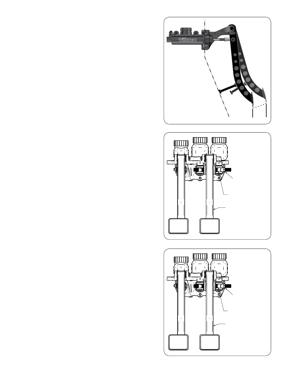
.25"
Diagram 4
clutch peDal setup
1. Install the clutch master cylinder using the supplied 5/16"-24 serrated flange nuts.
Make sure that there is a jam-nut on the pushrod.
2. Thread the pushrod into the rod end on the clutch pedal until the pedal is in the
desired position, which is usually a matter of driver preference.
A minimum of .25" thread engagement (6 threads) is recommended. You may need
to shorten the pushrod for some positions.
3. Tighten the master cylinder pushrod jam-nut against the spherical rod end.
4. Connect the hydraulic line to the master cylinder.
5. Fill the master cylinder reservoir with brake fluid. Do not use a silicone-based fluid.
6. Open the bleed fitting at the master cylinder, or loosen the line.
7. Gently depress and release the clutch pedal until fluid emerges.
8. Tighten the bleed fitting or line.
9. Fill the reservoir with brake fluid.
10. Place a light force on the pedal. You want enough to hold the bearing out against
the clutch diaphragm spring but not enough to compress it.
11. Open the bleed screw for the hydraulic release bearing.
12. Completely stroke the pedal.
13. Close the bleed screw.
14. Let the pedal return to its natural position and wait 4 seconds.
15. Repeat steps 10-14 until all air is removed from the system.
16. Proceed directly to setting the pedal stop before stroking the pedal again or the
clutch could be damaged. A pedal stop is usually required for small diameter racing
clutches and/or hydraulic release bearings with limited stroke.
clutch peDal stop setup
(For use with Tilton style hydraulic release bearings)
1. Install clutch pedal stop bolt, as shown in Diagram 6.
2. Raise the vehicle onto jack stands or a hydraulic lift.
3. With the engine off put the transmission into 1st gear and have someone attempt to
rotate one of the drive wheels.
4. Depress the clutch pedal slowly until the clutch disengages and the drive wheel can
be rotated.
5. Note the clutch pedal position at this point. This is labeled A in Diagram 4.
6. Adjust the pedal stop bolt to allow an additional 1/4" of pedal travel at the foot. This
is labeled as point B in Diagram 4. Secure the pedal stop bolt with jam-nut once
position has been set.
7. Adjust the pedal stop so the pedal cannot travel past point B.
Maintenance
Periodic inspections of the brake and clutch pedal assemblies should be conducted
routinely. Pay particular attention to the balance bar and pivot areas.
STIFF, LIGHTWEIGHT
TUBULAR STEEL
CLUTCH AND BRAKE
PEDALS
JAM NUT SECURES BIAS BAR SETTING.
FOR REMOTE CABLE ADJUSTER, REMOVE
JAM NUT AND SECURE CABLE TO END OF
BIAS BAR WITH CABLE COUPLER
CLEVIS DESIGNED FOR
MINIMUM FREE PLAY WITH
OR WITHOUT JAM NUTS
STIFF, LIGHTWEIGHT
TUBULAR STEEL
CLUTCH AND BRAKE
PEDALS
JAM NUT SECURES BIAS BAR SETTING.
FOR REMOTE CABLE ADJUSTER, REMOVE
JAM NUT AND SECURE CABLE TO END OF
BIAS BAR WITH CABLE COUPLER
CLEVIS DESIGNED FOR
MINIMUM FREE PLAY WITH
OR WITHOUT JAM NUTS
Diagram 5
Diagram 6