Tilton Firewall – Aluminum & Steel (98-1203) User Manual
Page 2
installation
1. Set the clevis center-to center distance at 2.620 +/- .040". You need to do
this before attaching the master cylinders.
2. Thread the adjusting shaft left or right until the spherical bearing is near
the center of the pivot sleeve. Note that the right end of the balance bar
has a longer threaded section and will stick out farther.
3. If you are using a remote adjuster, remove the jam-nut from the adjusting
shaft. If you are not using a remote adjuster, tighten the jam-nut against
the barrel nut on the longer end (right end) of the shaft. The round end
goes against the barrel nut.
4. Mount the pedal assembly in the car. It is important to mount the frame
rigidly so that it does not move when heavy pedal force is applied to both
pedals. See diagrams 5–8 for mounting hole locations. The four large
through holes are for attaching to the main support structure while the
two tapped holes and the six master cylinder mounting studs (which
often pass through a firewall) can be used for additional stiffening.
5. If you are going to bench bleed your master cylinders, now is the time.
6. Bolt the master cylinders into place with the supplied 5/16"-24 serrated
flange nuts. Make sure the master cylinder pushrod has a jam-nut.
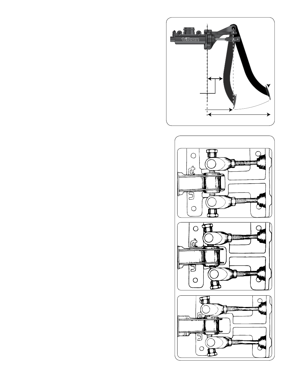
7. Thread the master cylinder pushrods into the clevises equal amounts
(you may need to alter this later) until the pedal foot pad is in the
correct position for the driver (See Diagram 2). A minimum of .25" thread
engagement (6 threads) is recommended.
8. Tighten the master cylinder pushrod jam-nuts against the clevises.
9. Make sure that the chosen pedal position allows a full 1" of stroke at both
master cylinders.
10. Make sure that the adjusted position also allows both master cylinders
to return to their fully relaxed position without binding. Preload on the
master cylinder pushrods can cause the brakes to lock up when hot when
there is no force on the pedal.
11. Attach hydraulic lines.
12. Attach the reservoirs and bleed as directed in the master cylinder
directions. With a balance bar, always bleed a front and a rear caliper at
the same time to insure total air removal.
13. Apply the brakes and adjust the pushrod length so the adjusting shaft is
parallel to the master cylinder mounting surface
(See Diagram 3). If one pushrod is shortened by one revolution,
lengthening the other by one revolution will maintain the same pedal
position. Do not extend the pushrods to the point where they preload
the master cylinder pistons. After adjusting, tighten the jam-nuts on both
pushrods.
14. You will need to test drive the vehicle to determine if adjustments need
to be made to the brake bias (front/rear brake force distribution). See
Section F for making bias adjustments.
Diagram 3
FIREW
AL
L
GAP REQUIRED
9.5" MINIMUM
PED
AL
AT
REST
MASTER CYLINDER
BOTTOMED
11.75"
Diagram 2
3.1
Pedal De-
pressed
Balance Bar
not at an
angle
(Correct)
3.2
Pedal De-
pressed
Balance Bar
at an angle
(Incorrect)
3.3
Pedal Re-
laxed
Balance Bar
may or may
not be
at an angle