Tilton Premium Oil Cooler Pump (98-1902) User Manual
Installation instructions, Oil cooler pump, Flow rate (gpm)
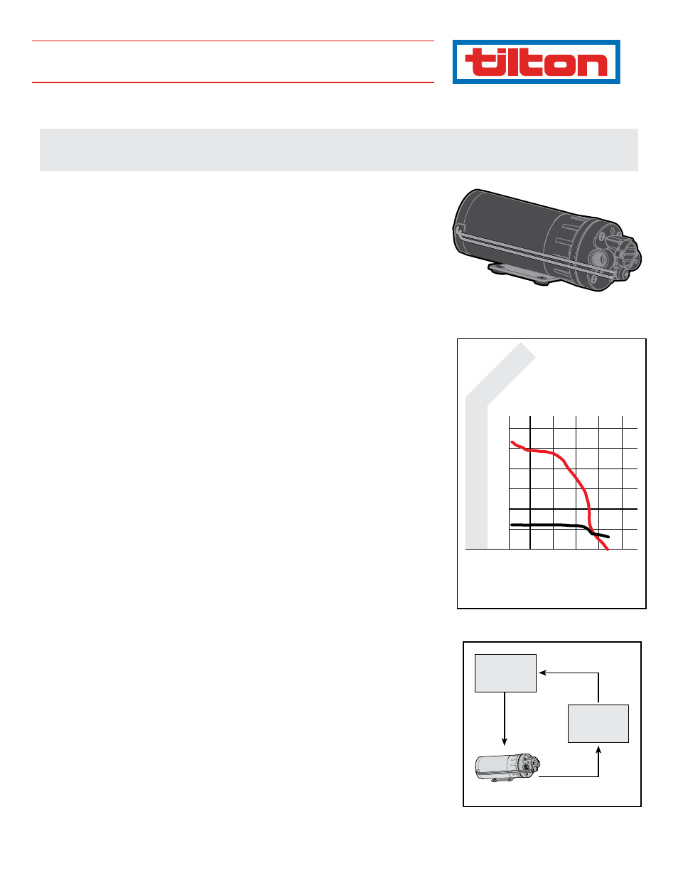
How It works
The Tilton Oil Cooler Pump is a positive displacement type of pump, so its output is directly proportional to
the motor speed. If a lighter load increases the motor speed by 25%, then the flow rate increases by 25%.
The flow rate vs. pressure is shown in Graph 1 with a maximum available pressure of 50 PSI. A fluid system
will only flow as much as the smallest restriction will allow. Larger diameter lines and fittings allow more
flow and place less load on the pump. This pump is self-priming and can be placed up to 8 ft above the
source from which it draws. The typical application for the pump is in a differential or transmission cooling
system. A 12-volt DC, 8-amp power supply is required. The current draw is 6 amps under a maximum load
condition with a more typical current draw between 3 and 4 amps. This pump weighs approximately 6 lbs
and is rated for continuous duty. The diaphragm and other internal seals are made of BUNA and the pump
head is Nylon. This pump is not designed to pump corrosive fluids including gasoline or diesel fuel.
InstallatIon notes
The Tilton Oil Cooler Pump is placed inline with the cooling system as shown in Diagram 1. Placing the
pump on the outlet side of the cooler exposes it to lower temperatures significantly increasing the life
and reliability of the pump. A 40-mesh (400 micron) strainer or filter placed inline before the inlet of the
pump prevents foreign objects from damaging the pump. Heavy gear oil must be brought up to operating
temperature before the pump is engaged. The cold fluid can be very thick and place an unusually large
strain on the pump. Tilton recommends the use of an on/off switch so the pump can be turned off during
warm-up periods. If the pump is mounted in a vertical position, mount the pump with the motor above
the pump inlet and outlet to prevent damage to the motor in the event of a fluid leak. The pump head can
be rotated in 180-degree increments, allowing a variety of hose positions. Be careful not to damage the
plastic pump housing by over tightening the fittings. If a check valve is placed inline with the pump, the
check valve must have an opening pressure of no more than 2 PSI. The electrical hook-up is simple. Con-
nect the pump to a 12-volt DC supply with a 8-amp fuse inline with the (red) positive lead. The black lead is
the chassis ground.
operatIon
• Allow the pump to prime with the discharge line open to prevent airlock.
• The pump will not be harmed if it is allowed to run dry. It is self-priming.
• This pump has an internal pressure relief valve and will automatically recirculate the within the pump
when 50 psi is reached.
plumbIng
• For best results, use a flexible AN8 (10mm) steel braided hose.
• Use only 3/8" NPT aluminum fittings at the pump inlet and outlet. Be careful not to over-tighten the
fittings and damage the pump housing.
• A 40 mesh (400 micron) filter should be used inline before the inlet of the pump.
electrIcal
• Use a minimum of 16AWG stranded wire for power connections.
• Use a 10-amp inline fuse on the 12-volt DC (red) power connection.
• The IP class for the electronics is -5- which is for dust only (pump is NOT water proof).
addItIonal Info
• Fluid can only pass through pump head in the flow direction when pump is turned off. However, back
flow of residual fluid in lines going to pump can occur.
• Use a 10-amp inline fuse on the 12-volt DC (red) power connection.
Diff/Trans
Cooler
Differential
or
Transmission
Diagram 1
Graph 1
Graph 1
Flow: 1.9 GPM (7.2 LPM) MAX | Pressure: 50 PSI (3.4 BAR) MAX | Voltage: 12 VDC | Current: 8 AMPS
Temperature range: 40–160˚ F Continous; 265˚ F (MAX) Intermittent | Prime: Self-priming up 8.0 ft (2.6 m) vertical height
Flow Rate (GPM)
60
50
40
30
20
10
30
25
20
15
10
5
AMPS
(A)
HEAD
(PSI)
0.4 0.8 1.2 1.6 2.0
(40-527)
Oil Cooler Pump
INSTALLATION INSTRUCTIONS
98
-19
02