Service checklist troubleshooting chart – Star Water Systems 433063 User Manual
Page 2
2
© 2011. All rights reserved.
1. Electrical wiring must be in accordance with the National Electrical Code
and all other applicable state and local electrical requirements.
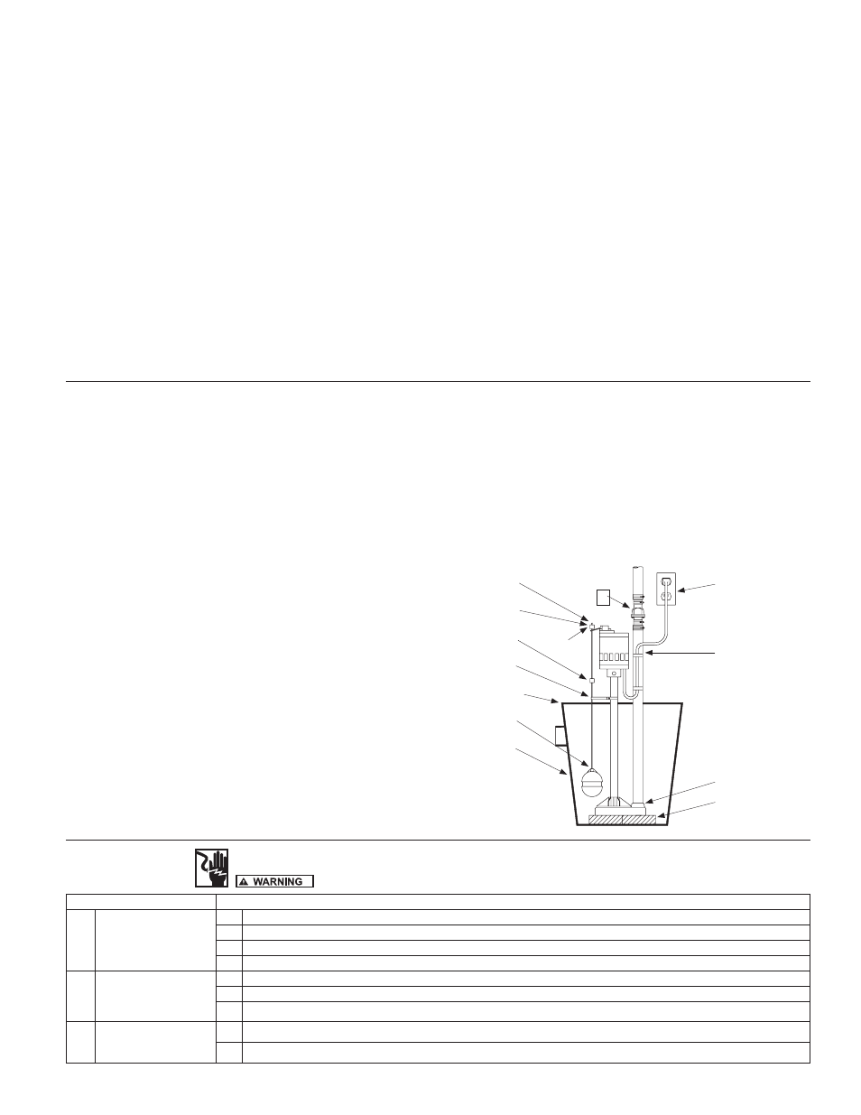
2. Install combination check valve and union preferably just above the sump
pit to allow easy removal of the pump for cleaning or repair.
3. Minimum pit size recommended is 18” diameter and 22” deep.
4. Locate float rod guide locator hole about midpoint of the column. Snap
float rod guide on to column at this location making sure that the nub on
the guide snaps into the hole.
5. Unscrew float from the float rod. Insert threaded end of float rod down
through eye of rod guide and screw float full back on the float rod.
6. Remove top rubber stop from float rod.
7. Pass rod through eye of pump switch.
8. Slide top rubber rod stop back onto the float rod flush with top after
passing through eye of switch. WARNING: Risk of flooding. Be sure that
float rod is vertical and can move up and down freely. If float is angled or
binds, pump may not start, allowing flooding to occur.
9. If the lower rod stop is positioned approximately 8” from the top of the rod,
the pump will automatically cycle on at a water level about 10 -12” and off
approximately. For faster cycling, move lower rod stop closer to switch
lever arm.
10. Thread pipe in discharge of pump. Use care not to cross thread or strip the
threads. Use a full-size discharge pipe.
11. Clean basin free of debris after installation.
12. Install blocks or bricks under pump to provide a settling basin.
13. Place pump in center of sump pit.
14. Securely tape or clamp power cord to discharge pipe clear of float
mechanism.
15. Check for proper ON-OFF switch operation by running water into the sump
pit.
16. All installations require a proper basin cover to prevent debris from falling
into the basin and to minimize accidental injury.
IL0726
CAuTION:
CHECK ROD AND FLOAT FOR FREE SwITCH OPERATION
TO ENSuRE THAT PuMP wILL TuRN ON AND OFF.
1
2
6
7
8
9
4
16
5
3
11
12
10
13
14
This product is warranted for one year from the date of purchase or two years from
the date of manufacture, whichever occurs first. Subject to the conditions hereinafter
set forth, the manufacturer will repair or replace to the original consumer, any portion
of the product which proves defective due to defective materials or workmanship. To
obtain warranty service, contact the dealer from whom the product was purchased.
The manufacturer retains the sole right and option to determine whether to repair or
replace defective equipment, parts or components. Damage due to conditions beyond
the control of the manufacturer is not covered by this warranty.
THIS WARRANTY WILL NOT APPLY: (a) To defects or malfunctions resulting from
failure to properly install, operate or maintain the unit in accordance with printed
instructions provided; (b) to failures resulting from abuse, accident or negligence or
use of inappropriate chemicals or additives in the water; (c) to normal maintenance
services and the parts used in connection with such service; (d) to units which are
not installed in accordance with normal applicable local codes, ordinances and
good trade practices; and (e) the unit is used for purposes other than for what it was
designed and manufactured.
RETURN OF WARRANTED COMPONENTS: Any item to be repaired or replaced
under this warranty must be returned to the manufacturer at Kendallville, Indiana or
such other place as the manufacturer may designate, freight prepaid.
THE WARRANTY PROVIDED HEREIN IS IN LIEU OF ALL OTHER EXPRESS
WARRANTIES, AND MAY NOT BE EXTENDED OR MODIFIED BY ANYONE. ANY
IMPLIED WARRANTIES SHALL BE LIMITED TO THE PERIOD OF THE LIMITED
WARRANTY AND THEREAFTER ALL SUCH IMPLIED WARRANTIES ARE
DISCLAIMED AND EXCLUDED. THE MANUFACTURER SHALL NOT, UNDER
ANY CIRCUMSTANCES, BE LIABLE FOR INCIDENTAL, CONSEQUENTIAL OR
SPECIAL DAMAGES, SUCH AS, BUT NOT LIMITED TO DAMAGE TO, OR LOSS
OF, OTHER PROPERTY OR EQUIPMENT, LOSS OF PROFITS, INCONVENIENCE
, OR OTHER INCIDENTAL OR CONSEQUENTIAL DAMAGES OF ANY TYPE OR
NATURE. THE LIABILITY OF THE MANUFACTURER SHALL NOT EXCEED THE
PRICE OF THE PRODUCT UPON WHICH SUCH LIABILITY IS BASED.
This warranty gives you specific legal rights, and you may have other rights which
vary from state to state. Some states do not allow limitations on duration of implied
warranties or exclusion of incidental or consequential damages, so the above
limitations may not apply to you.
WARRANTY VALID IN CANADA AND MEXICO.
TyPICAL COLuMN SuMP PuMP INSTALLATION
LIMITED wARRANTy
CONDITION
COMMON CAUSES
A.
Unit will not start
1. Check circuit protection.
2. Check electrical current supply to make sure it is the same as on the pump specification plate
3. Check rod and float for free ON-OFF switch operation. Readjust rod stops or guide if necessary
4. Check ON-OFF switch operation by running water into basin
B.
Unit starts or sounds
like it is running but will
not pump
1. Clear intake and discharge. Run to test operation.
2. Check to see that vertical lift of installation is within pump capacity. (Refer to pump capacity chart on page 1).
3. Check impeller for proper rotation. (Clockwise when viewed from motor end).
C.
Unit stops and starts
excessively
1. Install a proper check valve to prevent back flow from piping.
2. Check dimensions of basin as listed on previous page, Item 3.
UNPLUG PUMP BEFORE HANDLING PUMP OR PIPING
SERVICE CHECKLIST TROubLESHOOTING CHART