Electrical system parts breakdown, Pws-100 wiring instructions, Model # pws-100 – SnowEx PWS-225 User Manual
Page 8
© Trynex International 2010 L1217
AS — 8
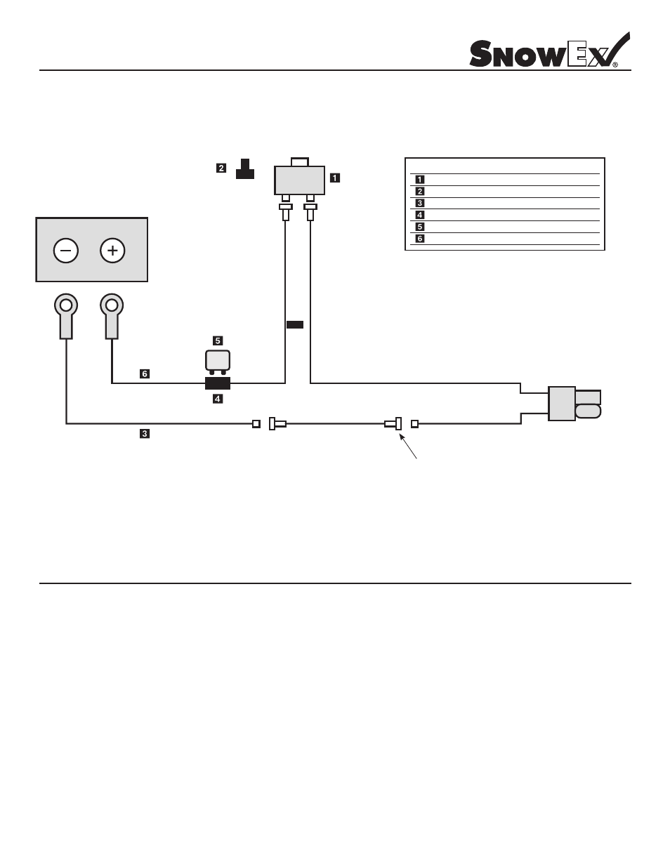
Electrical System Parts Breakdown
Model # PWS-100
PWS-100 Wiring Instructions
Step 1: First, install switch at desired location.
Step 2: Run spreader/vehicle harness from the rear of vehicle to switch area. Attach the female spade red wire to the switch.
leave the black wire for Step 5.
Step 3: Route the power harness from the battery to the switch/control.
Step 4: Attach the red lead to the positive side of the battery and the black lead to the negative side of the battery.
Step 5: Attach the female spade red wire on switch terminal. Using 3" double female black wire jumper, attach the black wire
from the power harness to the black wire of the vehicle harness.
Step 6: Install rubber weatherproof boot on switch before finishing installation.
Step 7: Insert dielectric grease on terminals of SAE plug at rear of vehicle.
25
AMP
BATTERY
REMOVE JUMPER FOR USE
WITH VAR-020 VARIABLE
SPEED CONTROLLER KIT
DOUBLE FEMALE
3" JUMPER
Key Part No.
Description
Qty.
D 6184
On/Off Switch 1
D 6406
Rubber Switch Boot 1
D 6719
Wiring Harness 1
D 6425
Fuse Holder 1
D 6482
25 Amp Circuit Breaker 1
D 7105
3/8" Ring Terminal 2