Chute/wet boom nozzle installation instructions – SnowEx PWS-225 User Manual
Page 24
© Trynex International 2010 L1217
AS — 24
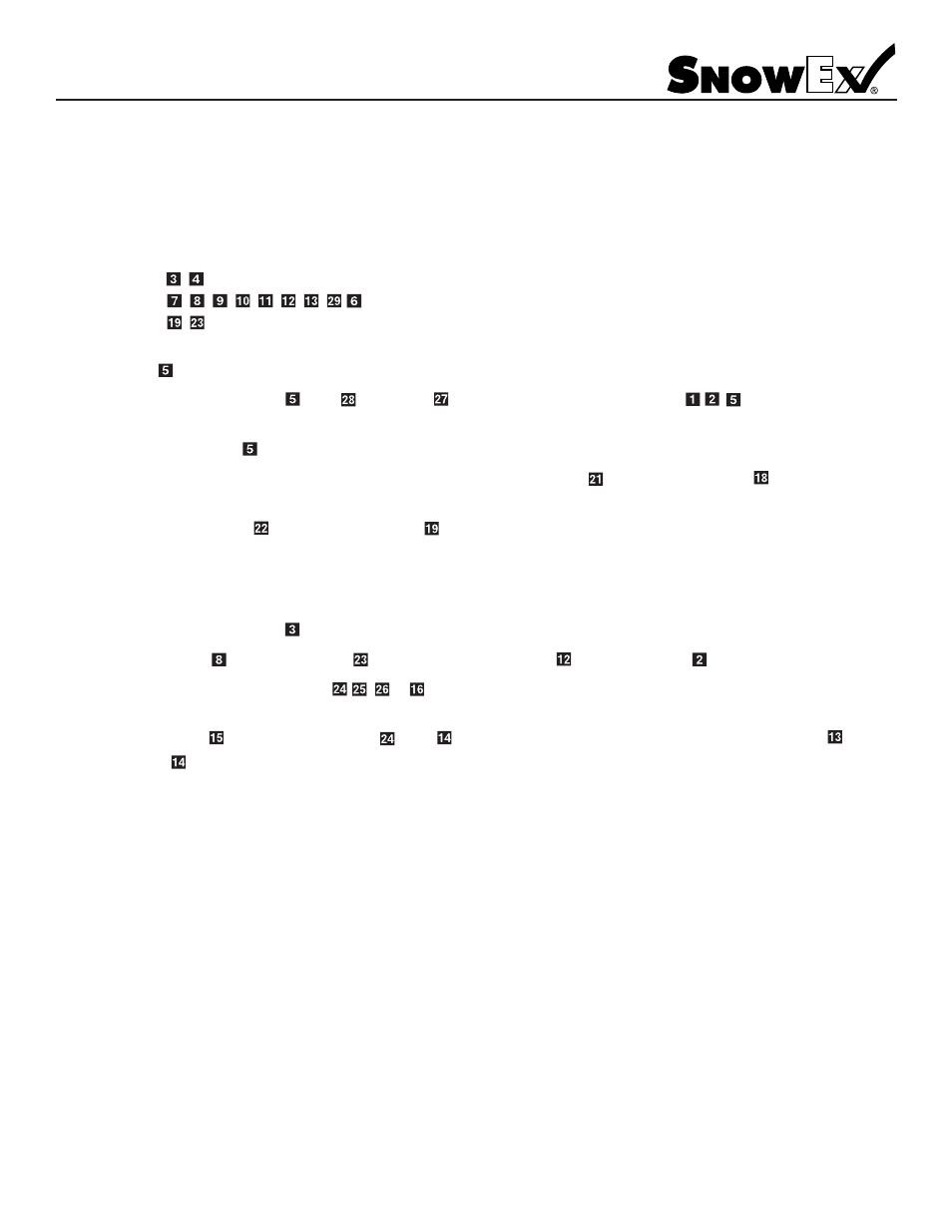
Chute/Wet Boom Nozzle Installation Instructions
Model # PWS-175/PWS-225
REFER TO PAGE AS-22 FOR DIAGRAM
Section C has three sub-assemblies pre-assembled from the factory. This is done in order to minimize installation time
during the final phase of assembly. They are made up in the following order.
Sub-Assembly A: ,
Sub-Assembly B: ,
, , , , , , ,
Sub-Assembly C: ,
Step 1: Install to bulkhead mounting bracket to V-Maxx right rear corner post (see page AS-4 upper photo).
Step 2: Attach sub-assembly A to using gasket and jam nut. At this time you can install , , from the last
instructions in Section B.
Step 3: Cut to length hose from section B (page AS-10) connect using hose clamps.
Attach sub-assembly B to
, keep assembly vertical and square to rear of V-Maxx frame.
Step 4: Attach sub-assembly C to V-Maxx spinner guard tube using nylon zip tie and wet boom bracket . Snug zip ties
as needed.
Step 5: Attach rotary nozzle to wet boom assembly . Note holes in boom need to align with rotary nozzle hole with o-ring
Step 6: When alignment is correct, tighten each rotary assembly until snug. DO NOT overtighten these assemblies.
Step 7:
Connect hose
to wet boom barb and to sub-assembly B barb using hose clamp . Trim hose as needed.
Step 8:
Assemble chute nozzle assembly , , to chute nozzle bracket. Attach assembly to V-Maxx driver/spinner
assembly. (See page AS-16 for reference.)
Step 9:
FINAL ASSEMBLY INSTRUCTIONS
Step 1: Make sure control power switch is in the OFF position and attach power leads to battery, Red-Positive, Black-to Ground.
Step 2: Fill tank with at least 10 gallons of water to test and flush system.
Step 3: Open rotary valves to high flow streamer position and also pre-wet system. This will achieve maximum flow through the
Step 4: Check system for any leaks and correct as needed.
Step 5: Run system until water has been depleted.
Step 6: Remove strainer element from filter assembly between the tank and pump, inspect and clean as needed. Replace strainer
and tighten bowl. Use minimal force to install bowl; o-ring seal does not require large amount of force to seal. Overtightening
will damage o-ring seal.
Step 7: Your de-ice/anti-ice/pre-wet system is now ready to be used with a wide variety of products. As with all chemicals,
consult the original manufacturer's handling, storage and usage instructions. Your local Trynex dealer will have information
regarding where to obtain materials for your system.
Step 10: Connect hose to pre-wet nozzle body using hose clamp. Connect the other end of sub-assembly B to
using hose clamp
.
INSTALL SPREADER - REFER TO TO SPREADER MANUAL FOR PROPER INSTALLATION
(See page AS-17 upper photo).
seal.
system.