Adjustments – RIKON Power Tools 25-200H User Manual
Page 17
17
ADJUSTMENTS
To inspect, adjust or change the drive belts:
1. Make sure that the planer/jointer's switch is turned off,
and the plug is disconnected from the power source.
2. Pull the fence forward, and remove the side panel and
belt cover to expose the motor, pulleys and belts. FIG. 29.
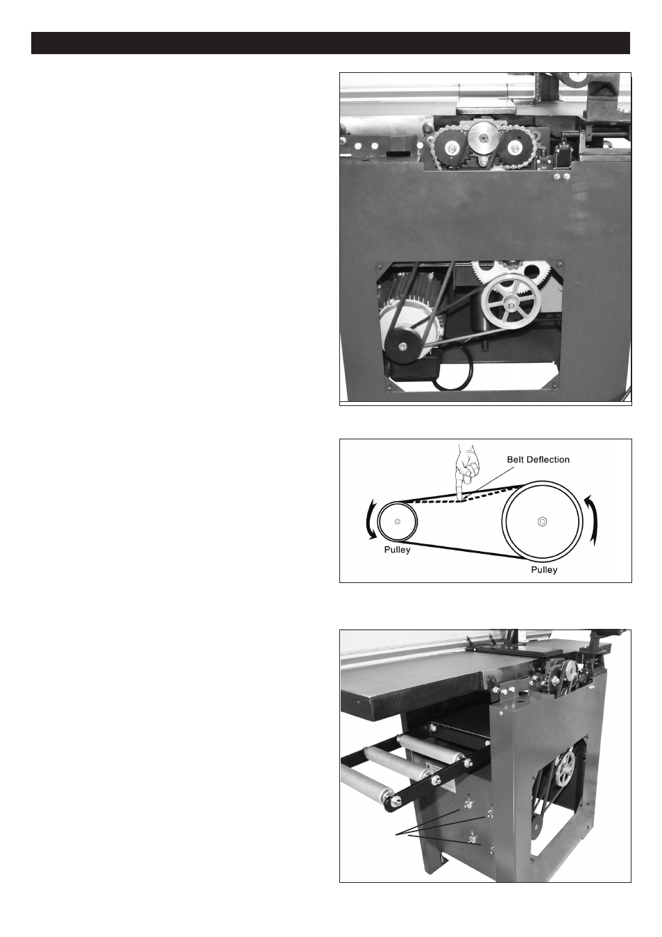
TENSIONING THE DRIVE BELTS
3. Check the
Cutterhead Drive Belt (#222, FIG. 30, A)
tension with thumb pressure. The drive belt should not give
more than 3/8" in the center. FIG. 31.
4. From outside, rear of the machine, loosen the four Nuts
(#223, FIG. 32) that secure the motor in place. Lift the
motor to slacken the tension on the drive belt, or move it
down to increase the belt tension.
5. When the belt tension is correct, tighten the motor
mounting nuts that were done in step 4.
6. The
Feed Roller Belt (#220), FIG. 30, B) is automati-
cally tensioned with the Spring (#248, C) and requires no
adjustments.
7. The
Feed Roller Chain (#228, FIG. 30, D) is factory set
and should not require any setting changes. However, to
increase or decrease the chain overlap, the Bearing with
Sleeve (#230, E) can be adjusted in or out with Bolt & Nut
(#233, 229).
NOTE: While the side panel and cutterhead cover are
open, remove any chips and dust that may have accumu-
lated with a dust collector or brush.
8. When all belts have been checked and any maintenace
has been done, replace the side panel and belt cover and
secure them in position with the screws.
REPLACING THE DRIVE BELTS
1. To replace the
Drive Belt (#222), follow the same steps,
#3-5 above. Loosen the tension until the belt can be easily
removed from the Motor Pulley (#221) and Cutterhead
Pulley (#235). Once removed, reverse the steps to install
and re-tension the new belt on the pulleys.
2. To replace the
Feed Roller Belt (#220), the Drive Belt
must first be removed. With the motor loose and lifted,
there should be enough slack to install a new Feed Roller
Belt. If not, the tensioning Spring (#248) can also be
un-hooked to allow the Cam Wheel Bracket (#244) to
swing loose. Re-fastened the spring once the belt has
been installed. Then reverse the steps to install the drive
belt and re-tension it on the pulleys.
3. When all work on the belts has been done, replace the
side panel and belt cover and secure them in position with
the screws.
D
Drive Belt Adjustment continued from page
16
FIG. 30
FIG. 32
FIG. 31
MOTOR
MOUNTING
NUTS
A
B
C
D
E