Adjustments – RIKON Power Tools 25-200H User Manual
Page 10
ADJUSTMENTS
JOINTER FENCE ADJUSTMENT
The jointer fence provides lateral support for the workpiece
when surface planing.
1. After loosening the Locking Handle (#292, FIG.7, A),
the jointer fence can be moved forward or backwards over
the jointer bed and cutterhead, to match the workpiece
width.
2. The jointer fence can be tilted to any angle between
90°- 45°. To adjust the fence angle, loosen the ratchet
Locking Handle (#291, B) and Pin Stop Knob (#288, C).
3. Tilt the fence to the angle desired, then re-tighten
the locking handle (B) to ensure the fence is securely in
position. The pin stop knob only secures the fence in the
90° position, so is not active when the fence is set at an
angle.
B
A
C
FIG. 7
FIG. 10
FIG. 9
FIG. 8
10
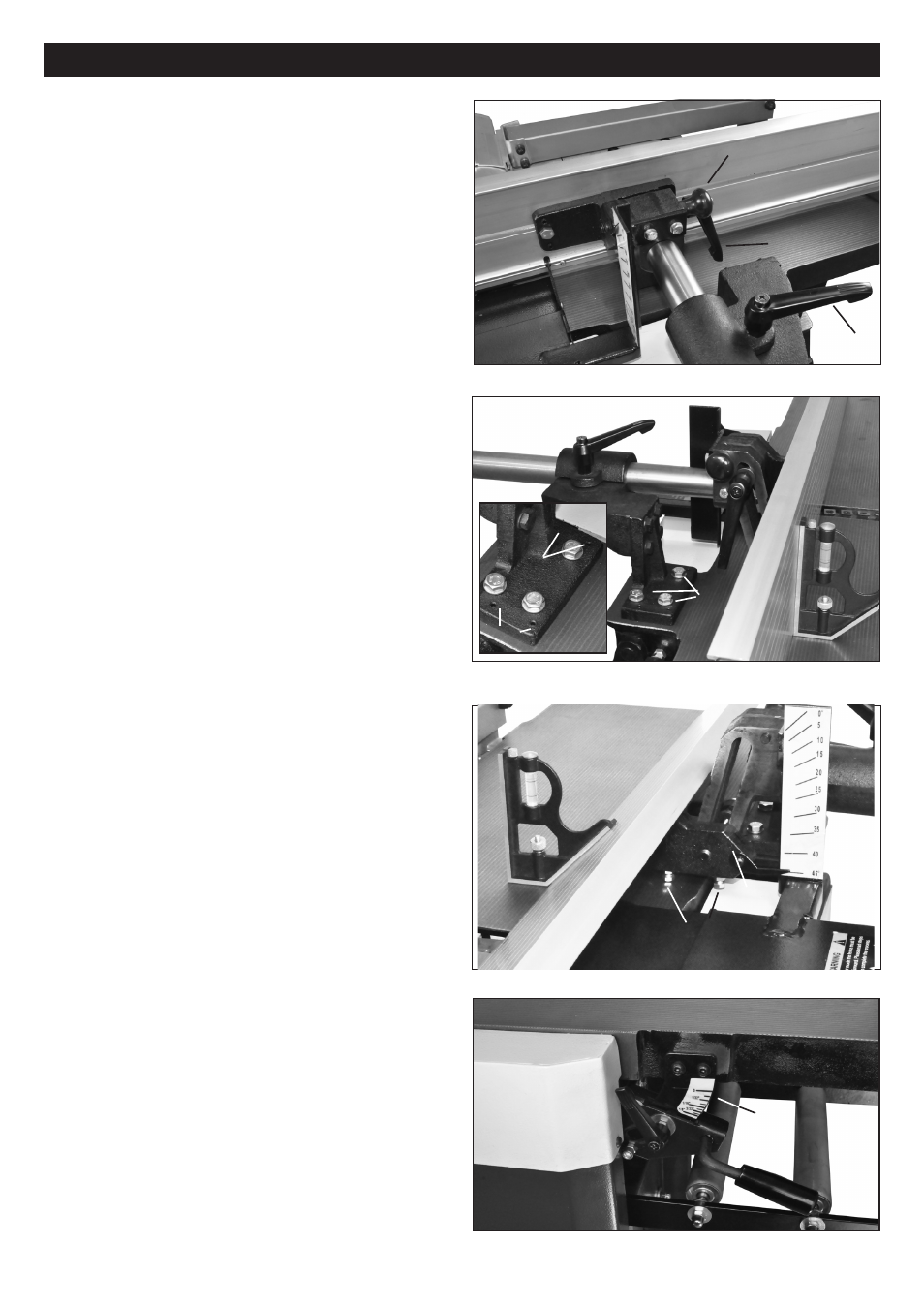
SETTING THE FENCE TO 90° & 45°
4. To set the fence at 90° to the table surface, set a try
square (FIG. 8, D) against the fence extrusion (E).
5. Lightly loosen the three Hex Bolts (#294, F) on the
base of the Sliding Bracket (#293, G), and adjust the Set
Screws (#152, H) until the fence is square with the jointer
table. Adjust the set screws in pairs, with the same amount
of rotations. The two forward set screws will tilt the fence
slightly backwards, and the two rear set screws will tilt the
fence forward.
6. When the fence extrusion is exactly 90°, tighten the
hex bolts to secure the fence assembly in position.
7. To set the fence at exactly 45° backwards, set a miter
square (FIG. 9, H) against the fence extrusion. This angle
is actually 135° from the jointer table.
8. There are two Hex Bolts (#302, FIG 9, I) at the bottom
of the Fence Bracket (#283, J) that touch the table when
at the 45° setting. Ajust the hex bolts until the fence
extrusion is exactly set at 45°, then secure the bolts in
position with their Hex Nuts (#301).
INFEED TABLE HEIGHT ADJUSTMENT
The jointer's Infeed Table (#92, FIG. 10, K) is adjusted up
and down by using the adjusting Lever (L). This regulates
the cutting depth for edge jointing and surface planing.
1. Loosen the Locking Handle (#105, M).
2. Move the Lever (L) to raise or lower the table. The
Scale (#341, N), located next to the adjusting lever,
corresponds to the depth of cut - how much material is
being removed - from 0" to 1/8".
3. After adjustment to the table height that you desire,
tighten the locking handle to secure the table in position.
NOTE: Never make cuts deeper than 1/8”. Multiple cuts,
1/16" or less, produce better finish results.
G
K
L
N
M
H
I
J
D
E
F
H
H