Adjustments, Fig. 17 – RIKON Power Tools 25-200H User Manual
Page 12
12
ADJUSTMENTS
ROTATING OR REPLACING KNIFE INSERTS
This machine has a helical cutterhead with four rows of
carbide knife inserts. Each of the 56 inserts on the
cutterhead are indexed and have four sharpened sides.
If the knives become dull, or one becomes nicked, simply
loosen the retaining screws with the supplied star head
screwdriver, lift up and rotate the inserts to a new sharp-
ened edge. No setting is required, as the cutterhead has
been machined to automatically index and set the inserts in
proper position for use. When all four sides of an insert are
dull, the insert can be easily removed and a new carbide
insert placed in the location.
To rotate or remove a carbide insert knife:
1. Unplug power cable.
2. Remove the Screw (#350), that holds the Insert in the
cutterhead, and the Insert knife (#349). FIG. 14.
3. While the insert is removed, clean any resin buildup or
trapped dust from the surfaces of the cutterhead with a
suitable solvent. A tooth brush works well for safe cleaning
around the sharp inserts. Any accumulated dust can affect
the seating of the insert in the cutterhead.
4. Rotate the insert so that a new sharpened edge is in
position. The inserts have a indication mark on their top
surface corner, so that you can reference the positioning of
the insert's dulled or sharpened edges. FIG. 14, 15, 16.
5. Tighten the insert's set screw to lock the insert back in
position. DO NOT overtighten the screw or damage to the
insert may result. Torque to 50-55 in/lbs.
6. Plug in the power cable when you are ready to
resume jointing and planing.
FIG. 15
FIG. 16
FIG. 14
CARBIDE INSERT
KNIFE HAS 4
SHARP EDGES
INDEX MARK
STAR HEAD
SET SCREW
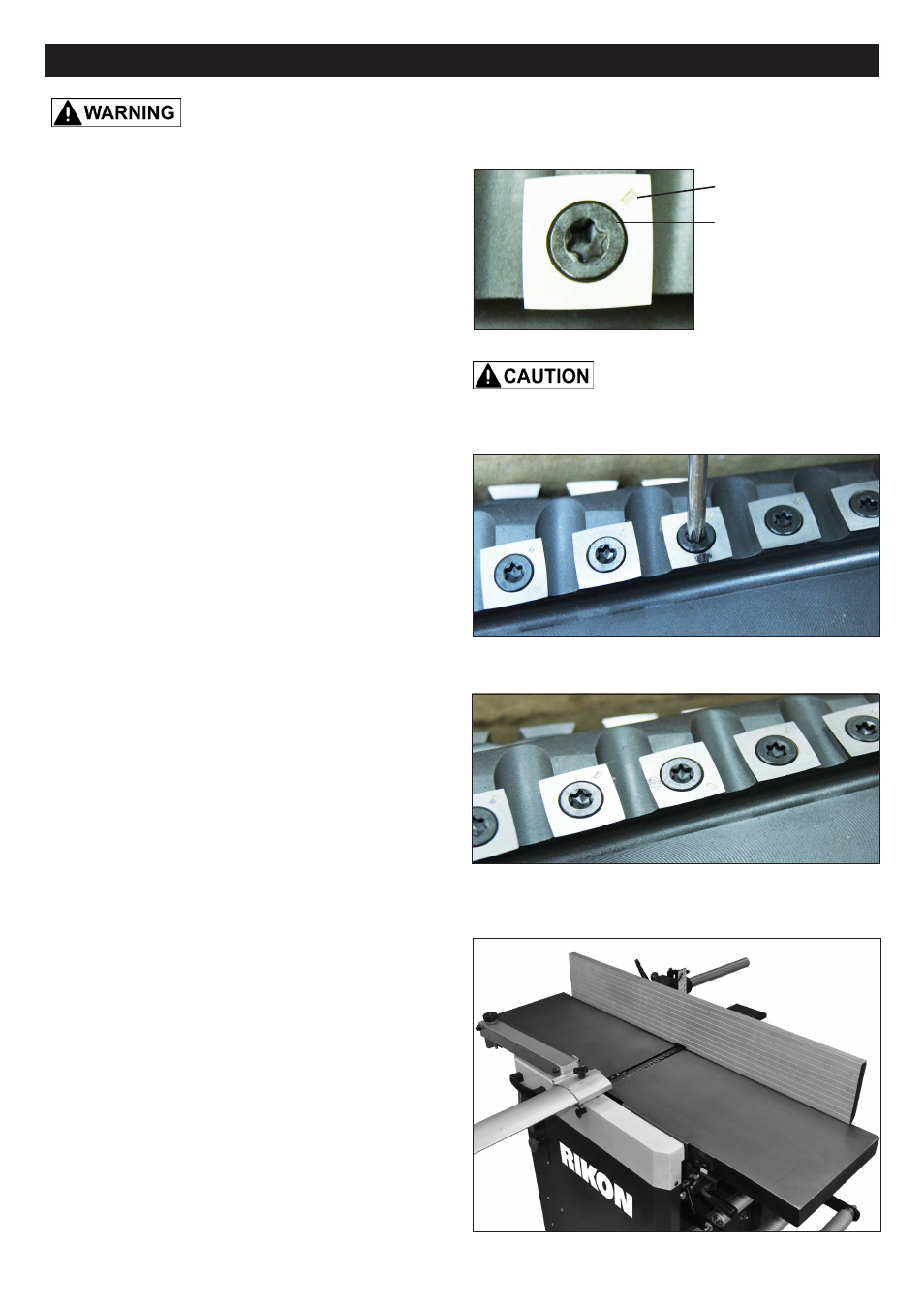
JOINTER TABLE ALIGNMENT
For the best surfacing of workpieces, the jointer's infeed
and outfeed tables must be set at the same level to form a
large 'flat' surface. These tables must also be in alignment
with the cutterhead for true surfacing, when you measure
the flatness of a board from side-to-side and end-to-end.
The machine has been factory set before shipping - the
infeed table being set to the cutterhead knives, and then
the outfeed table set to the infeed table. But once the ma-
chine has been set in its final location in the shop, the table
alignments should be checked to make sure that there has
been no movement during its handling.
1. Position and lock the infeed table at its high '0" ' setting,
so that it should be level with the outfeed table.
2. Slide the fence and cutterhead guard to the sides and
off the tables to reveal the whole table surfaces. FIG. 17.
THE MACHINE MUST NOT BE PLUGGED IN AND THE POWER SWITCH
MUST BE IN THE OFF POSITION UNTIL ADUSTMENTS ARE COMPLETE.
FIG. 17
Wear gloves when changing knife
inserts to avoid the risk of personal injury by cuts that may
result from touching the sharp edges!
continued on page 13