Site selection & preparation, Arch assembly – Rhino Shelter ROUND-30W X 40L X 15H User Manual
Page 3
Assembly Instructions
30x40x15 Round Style Portable Building With Single Door
3
Version 2.0
Please DO NOT return unit to store or dealer. For all questions or shortages please contact
Customer Service at: 800-447-7079 or 203-877-7070
SITE SELECTION & PREPARATION
Select a level or as close to level as possible location for
your MDM Products Building. As the components fit into
each other as a level unit, there can be no more than 1
inch difference between one base flange and another.
Time spent preparing the base will pay off in years of
good operation without binding of parts and doors.
The best location is on top of a poured concrete pad. At
minimum, the building should be placed on a base of
materials suitable for the storage load to be protected. If
not on concrete, typical construction would be a 6” bed
of crushed process rock, compacted with a vibrating
compactor, with blocks underneath the location of the
base flanges. Sides can be mounted on top of wooden
timbers or piles driven into the ground at the correct
elevation.
The unit should not be located under trees, which will
shed hard fruit such as apples, walnuts, or heavy
pinecones. The cover of your unit will protect against
normal falling leaves and light debris; however, large
branches or other falling items may cause a puncture or
tear in the cover material.
Take notice of drainage around your intended location.
Water draining from the surrounding terrain should be
planned so that it does not run into the unit. As well, rain
or melting snow that comes off the unit should be
drained away rather than accumulate and pool around
the unit.
Check to be certain that adequate clearance is allowed
for entry and exit.
When selecting a location for the building, consideration
should be taken of the ability of the ground to keep the
base flanges in place, as well as support the weight of
the building and content. Using the stakes and string,
measure off and square area for intended installation.
Level the ground as best as possible. A properly leveled
frame yields maximum strength.
ARCH ASSEMBLY
Step #1 – Assemble Arches
Unit consists of One Front Arch, Five (5) Interior Arches,
and One Rear Arch. Assemble each arch on ground.
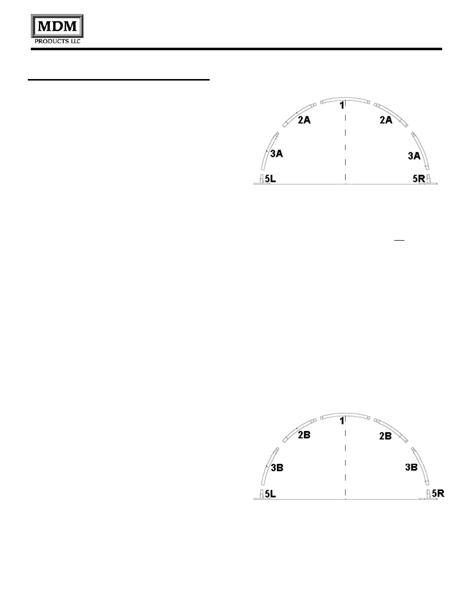
Begin by laying out the components of the Front Arch.
Front Arch consists of:
One (1) Top Ridge Tube (1)
Two (2) Front Wall Curved Roof Tube (2A)
Two (2) Front Wall Sidewall Tubes with Wind Brace
supports (3A)
Components slide into each other at the ends. Sidewall
tubes (3A) must be faced so the clips for Wind Brace
Supports are facing to the next interior arch. Secure
them together using 10mm x 75 mm Carriage Bolt,
washer, and nuts. Only snug up nuts, do not over
tighten nuts.
Use 10mm x 75mm Bolts with Washers and Nuts
through pre-drilled holes in frame members. Be certain
to insert carriage bolts from the outside into the interior
of the unit, with the washers and nuts on the inside of
the frame. This will prevent the bolts from puncturing
through the cover material. Do not tighten down the nuts
completely until frame is fully assembled and set in
place.
Assemble Rear Arch in same manner. Rear Arch
consists of:
One (1) Top Ridge Tube (1)
Two (2) Rear Wall Curved Roof Tube (2B)
Two (2) Rear Wall Sidewall Tubes with Wind Brace
supports (3B)
Assemble each of the five (5) Interior Arch Assemblies.
Refer to Figure 1 Frame Assembly to review Interior
Arch #2 and #6 requirements (directly inside End
arches). These aches must have the Sidewall Tubes