Operation, Controls and settings – Lincoln Electric IM657 RED-D-ARC DC-600 User Manual
Page 19
B-5
OPERATION
B-5
CONTROLS AND SETTINGS
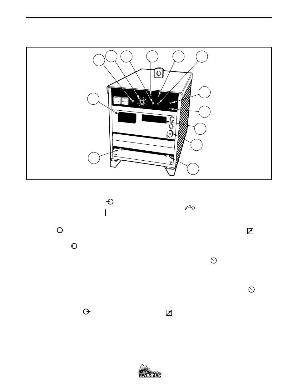
All operator controls and adjustments are located on the Case Front Assembly of the DC-600. See Figure B.1 for
the location of each control.
FIGURE B.1 - CONTROL PANEL KEYS
1.
Input POWER ON/OFF Switch
This toggle switch turns the machine on or off.
Putting the switch in the ON “ ” position ener-
gizes the machine’s input contactor applying input
power to the machine. Switching the switch to the
OFF “ ” position de-energizes the input
contactor.
2.
POWER Light
When the POWER switch is in the ON position the
machine’s red POWER light will illuminate. If the
input contactor de-energizes the machine in an
abnormal situation the pilot light will still illuminate.
In this situation it may be necessary to reset the
machine by switching the POWER switch to the
OFF and then to the ON position. (See Overload,
Overcurrent, and Fault Protection Section)
3.
OUTPUT CONTROL
This control provides continuous control of the
machine’s output voltage and current from mini-
mum to maximum (typical full pot range between
15 to 44 volts and 90 to 750 amps) as it is rotated
clock-wise. Voltage or current control is deter-
mined by setting of Mode Switch (CV or CC).
4.
OUTPUT TERMINALS ON/REMOTE Switch
When this switch is in the REMOTE “ ” posi-
tion, the DC-600’s output terminals will be electri-
cally “cold” until a remote device such as a wire
feeder closes the #2 and #4 circuit in the MS-
receptacle or terminal strip (T.S.2). When this
switch is in the ON “ ” position the machine’s
output terminals will be electrically energized all
the time.
5.
LOCAL/REMOTE Switch
When this switch is set to the LOCAL “ “ posi-
tion, control of the output voltage and current is via
the OUTPUT CONTROL on the DC-600’s control
panel. When this switch is set to the REMOTE
“ ” position, control is through a remote source
such as a wire feeder via the #75, #76, and #77
leads in the MS-receptacle or terminal strip
(T.S.1).
1
2
3
4
5
6
7
8
9
10
DC-600
13
12
7
5
11
2
1
4
9
8
6
3
10
DC-600