Operation, Auxiliary power, Warning – Lincoln Electric IM660 RANGER 200 User Manual
Page 19
Stick Welding
The RANGER 200 can be used with a broad range of
DC stick electrodes.
TIG Welding
The RANGER 200 can be used for limited DC
Tungsten Inert Gas (TIG) welding applications using
the scratch start procedure. Start the arc while the
engine is running at low idle. TIG welding is normally
done with electrode negitive.
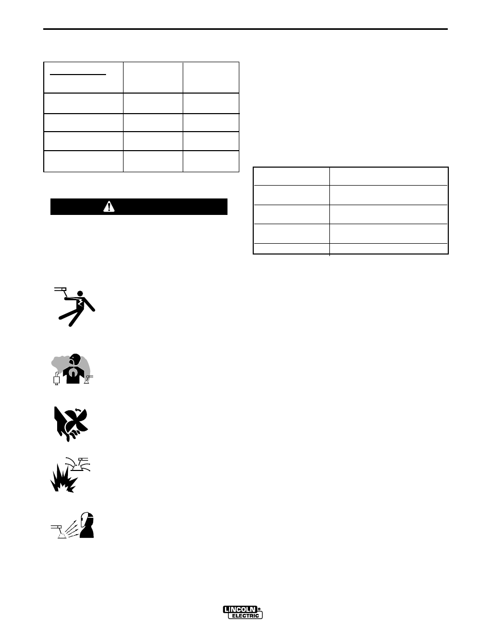
ARC GOUGING
Set the CONTROL knob to adjust output current to the
desired level for the gouging electrode being used
according to the ratings in the following table.
Electrode Diameter
Current Range (DC, electrode
positive)
1/8"
30-60 Amps
5/32"
90-150 Amps
3/16"
150-200 Amps
AUXILIARY POWER
Start the engine and set the IDLER control switch to
the desired operating mode. Full power is available
regardless of the welding control settings providing no
welding current is being drawn.
The auxiliary power of the RANGER 200 consists of
two 20 Amp-120 VAC (5-20R) duplex receptacles and
one 50 Amp 120/240 VAC (14-50R) receptacle. The
240 VAC receptacle can be split for single phase 120
VAC operation.
The auxiliary power capacity is 6,000 watts of 60 Hz,
single phase power. The auxiliary power capacity rat-
ing in watts is equivalent to volt-amperes at unity
power factor. The max permissible current of the 240
VAC output is 25 Amps. The 240 VAC output can be
split to provide two separate 120 VAC outputs with a
max permissible current of 25 Amps per output to two
separate 120 VAC branch circuits (these circuits can-
not be paralleled). Output voltage is within ± 10% at
all loads up to rated capacity.
The 120 V auxiliary power receptacles should only be
used with three wire grounded type plugs or approved
double insulated tools with two wire plugs. The cur-
rent rating of any plug used with the system must be
at least equal to the current capacity of the associated
receptacle.
NOTE: The 240 V receptacle has two circuits, each of
which measure 120 V toneutral but are of opposite
polarities and cannot be paralleled.
B-4
OPERATION
B-4
TABLE B.1
TYPICAL RANGER 200 FUEL CONSUMPTION
WELDING OPERATION
RANGER 200
Do not attempt to use this equipment until you
have thoroughly read the engine manufacturer’s
manual supplied with your welder. It includes
important safety precautions, detailed engine
starting, operating and maintenance instructions,
and parts lists.
------------------------------------------------------------------------
ELECTRIC SHOCK can kill.
• Do not touch electrically live parts
or electrode with skin or wet
clothing.
• Insulate yourself from work and
ground
• Always wear dry insulating gloves.
------------------------------------------------------------------------
FUMES AND GASES can be
dangerous.
• Keep your head out of fumes.
• Use ventilation or exhaust to
remove fumes from breathing zone.
------------------------------------------------------------------------
MOVING PARTS can injure.
• Do not operate with doors open or
guards off.
• Stop engine before servicing.
• Keep away from moving parts.
------------------------------------------------------------------------
WELDING SPARKS can cause fire or
explosion.
• Keep flammable material away.
------------------------------------------------------------------------
ARC RAYS can burn.
• Wear eye, ear and body protection.
------------------------------------------------------------------------
See additional warning information
throughout this operator’s manual.
-----------------------------------------------------------
WARNING
KOHLER CH 15
Low Idle - No Load
2500 RPM
High Idle - No Load
3700 RPM
DC CC Weld Output
210 Amps @ 25 Volts
Auxiliary Power,
6,000 VA
15 HP@3600
RPM GAL./HR
(LITERS/HR.)
.25 gallons/hour
(.95 liters/hour)
.52 gallons/hour
(2.0 liters/hour)
1.1 gallons/hour
(4.1 liters/hour)
1.0 gallons/hour
(3.9 liters/hour)
RUNNING
TIME 12 GAL.
(HOURS)
48
23
11
12