Operation, B-18, 4 step trigger operation – Lincoln Electric IM827 POWER FEED 10M WIRE FEEDER User Manual
Page 41
b-18
OPERATION
b-18
POWER FEED
®
10M SINGLE WIRE FEEDER
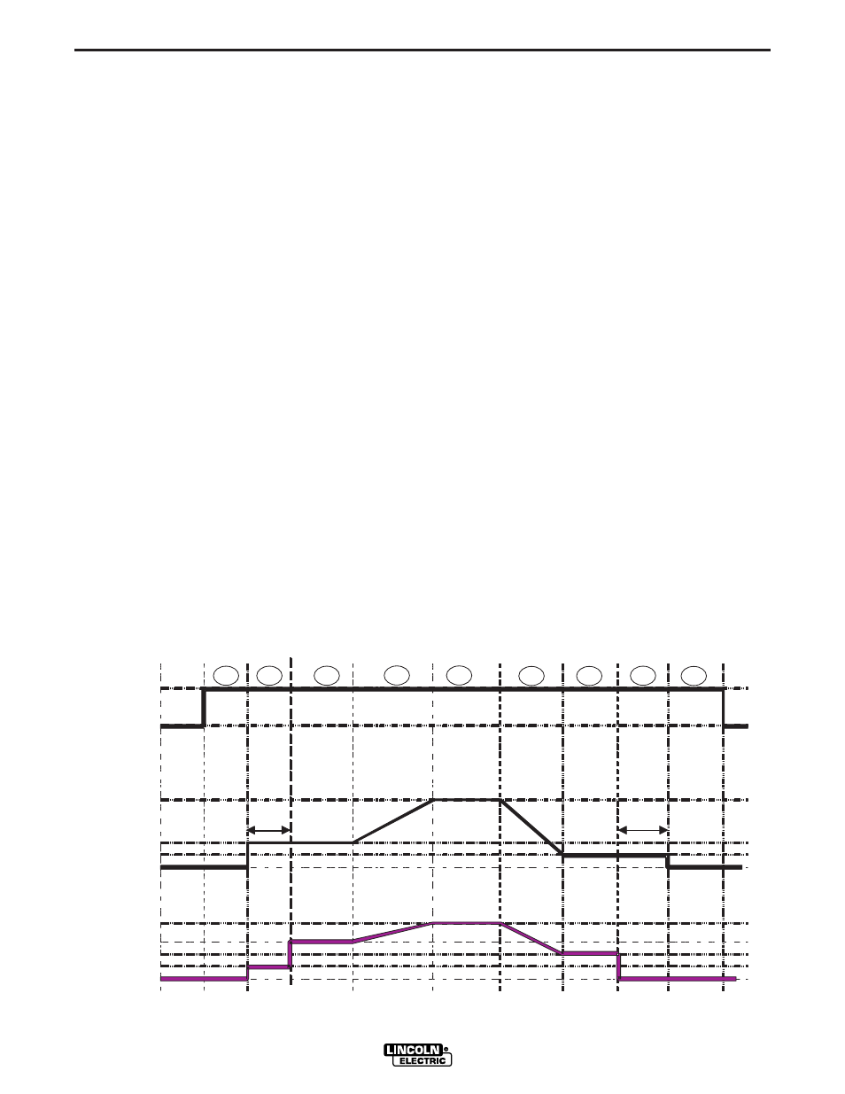
4 STEP TRIGGER OPERATION
(See Figure B.5)
The 4 step trigger sequence gives the most flexibility
when the Start, Crater and Burnback functions are
active. This is a popular choice when welding alu-
minum because extra heat may be needed during
Start and less heat desired during Crater. With 4 step
trigger, the welder chooses the amount of time to weld
at the Start, Weld and Crater settings by using the gun
trigger. Burnback reduces the likelihood of wire to
sticking in the weld pool at the end of a weld and also
prepares the end of the wire for the next arc start.
SEQUENCE OF OPERATION
Following is the total weld sequence that the Power
Feed
®
10M Single Wire Feeder will execute. If any
parameter is inactive or its time is set to zero, the weld
procedure immediately shifts to the next parameter in
the sequence.
1. PREFLOW: Shielding gas begins to flow immedi-
ately when the gun trigger is pulled.
2. STRIKE: After preflow time expires, the power
source regulates to the start output and wire is
advanced towards the work piece at the Strike
WFS. If an arc is not established within 1.5 sec-
onds, the power source output and wire feed speed
skips to the weld settings.
3. START: The power source welds at the “Start”
WFS and voltage until the trigger is released.
4. UPSLOPE: Once the trigger is released, both the
machine output and the wire feed speed ramp up or
down to the weld settings throughout the start time.
The time period of ramping from the Start settings
to the Weld settings is called UPSLOPE.
5. WELD: After Upslope, the power source output and
the wire feed speed continue at the Weld settings.
6. DOWNSLOPE: Then as soon as the trigger is
pulled, the wire feed speed and power source out-
put ramp to the crater settings during the crater
time. The time period of ramping from the weld set-
tings to the crater settings is called DOWNSLOPE.
7. CRATER: Alter the Downslope time expires, the
machine welds at the Crater WFS and voltage set-
tings until ether the trigger is released or the Crater
time expires.
8. BURNBACK: After the crater time expires, the wire
feed speed is turned OFF and the machine output
continues for the burnback time.
9. POSTFLOW: Next, the machine output is turned
OFF and shielding gas continues to flow until the
post flow timer expires.
S
Shi
hie
elld
diing
ng
Ga
Gas
s
Idle
Idle
Preflow
Preflow
Strike
Strike
Upslope
Upslope
Weld
Weld
Burnback
Burnback Postflow
Postflow
Idle
Idle
WFS
WFS
O
On
n
O
Off ff
S
Sttrriik
ke
e
O
Offff
W
Wel
eld
d
O
Offff
W
Wel
eld
d
Arc Arc
EstablishedEstablished
T
rigger
T
rigger
PulledPulled
T
rigger
T
rigger
ReleasedReleased
1.5 sec
1.5 sec
Max.
Max.
Burnback
Burnback
Time
Time
S
Stta
arr tt
Downslope
Downslope
C
Crrat
ater
er
P
Powe
owerr
S
Sou
ourrc
ce
e
Out
Out p
put
ut
C
Crrat
ater
er
Start
Start
T
rigger
T
rigger
PulledPulled
Crater
Crater
T
rigger
T
rigger
ReleasedReleased
S
Sttar
ar tt
2
2
1
1
3
3
4
4
5
5
6
6
7
7
8
8
9
9
FIGURE b.5