Operation, B-17, B-17 2 step trigger operation – Lincoln Electric IM827 POWER FEED 10M WIRE FEEDER User Manual
Page 40
S
Sh
hiie
elld
d iin
ng
g
G
Ga
as
s
IId
dlle
e
P
Prre
effllo
ow
w
S
Sttrrii k
ke
e
U
U p
ps
sllo
o p
pe
e
W
We
elld
d
B
Bu
u rrn
nb
ba
a c
ck
k
P
Po
os
sttffllo
ow
w
IId
dll e
e
W
WF
FS
S
O
On
n
O
Offff
R
Ru
un
n --iin
n
O
Offff
W
We
e lld
d
O
Offff
W
We
e lld
d
A
rc
Arc
E
s
ta
b
lis
h
e
d
Established
T
rigger
T
rigger
PulledPulled
T
ri
g
g
e
r
T
rigger
R
e
le
a
s
e
d
Released
1
1..5
5 s
se
ec
c ma
max
x ..
St
Sta
art
rt
S
Stt a
arrtt tt ime
ime
B
B u
urrn
nb
ba
ac
ck
k Time
Time
D
Do
o w
wn
n sl
slo
op
p e
e
C
Cra
ratte
e rr
C
Crra
atte
err ttii me
me
P
Po
ow
wer
er
S
So
o u
urrce
ce
O
Ou
utt p
pu
u tt
C
C ra
ratte
err
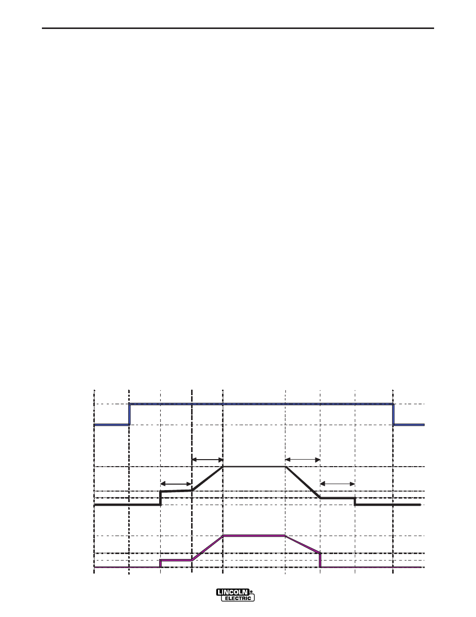
FIGURE b.4
b-17
OPERATION
b-17
2 STEP TRIGGER OPERATION
(See Figure B.4)
Sometimes it is advantageous to set specific arc start,
crater and arc ending parameters for the ideal weld.
Many times when welding aluminum crater control is
necessary to make a good weld. This is done by set-
ting Start, Crater and Burnback functions to desired
values.
SEQUENCE OF OPERATION
Following is the total weld sequence that the Power
Feed
®
10M Single Wire Feeder will execute. If any
parameter is inactive or its time is set to zero, the weld
procedure immediately shifts to the next parameter in
the sequence.
1. PREFLOW: Shielding gas begins to flow immedi-
ately when the gun trigger is pulled.
2. STRIKE: After preflow time expires, the power
source regulates to the start output and wire is
advanced towards the work piece at the Strike
WFS. If an arc is not established within 1.5 sec-
onds, the power source output and wire feed speed
skips to the weld settings.
3. UPSLOPE: Once the wire touches the work and an
arc is established, both the machine output and the
wire feed speed ramp to the weld settings through-
out the start time. The time period of ramping from
the start settings to the weld settings is called UPS-
LOPE.
4. WELD: After upslope, the power source output and
the wire feed speed continue at the weld settings.
5. CRATER: As soon as the trigger is released, the
wire feed speed and power source output ramp to
the crater settings throughout the crater time. The
time period of ramping from the weld settings to the
crater settings is called DOWNSLOPE.
6. BURNBACK: After the crater time expires, the wire
feed speed is turned OFF and the machine output
continues for the burnback time.
7. POSTFLOW: Next, the machine output is turned
OFF and shielding gas continues until the post flow
timer expires.
POWER FEED
®
10M SINGLE WIRE FEEDER